
Non-volatile photonic material and production method of the same

a non-volatile, photonic material technology, applied in the direction of camera filters, lighting and heating apparatus, instruments, etc., can solve the problems of limited use and production of such nanostructures in the field of non-volatile photonic materials

Inactive Publication Date: 2016-06-30
NAGOYA UNIVERSITY +1
View PDF1 Cites 7 Cited by
  • Summary
  • Abstract
  • Description
  • Claims
  • Application Information

AI Technical Summary

Benefits of technology

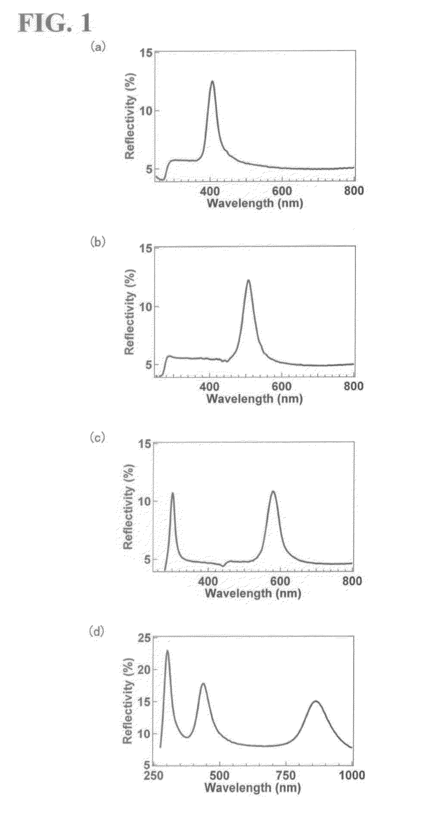
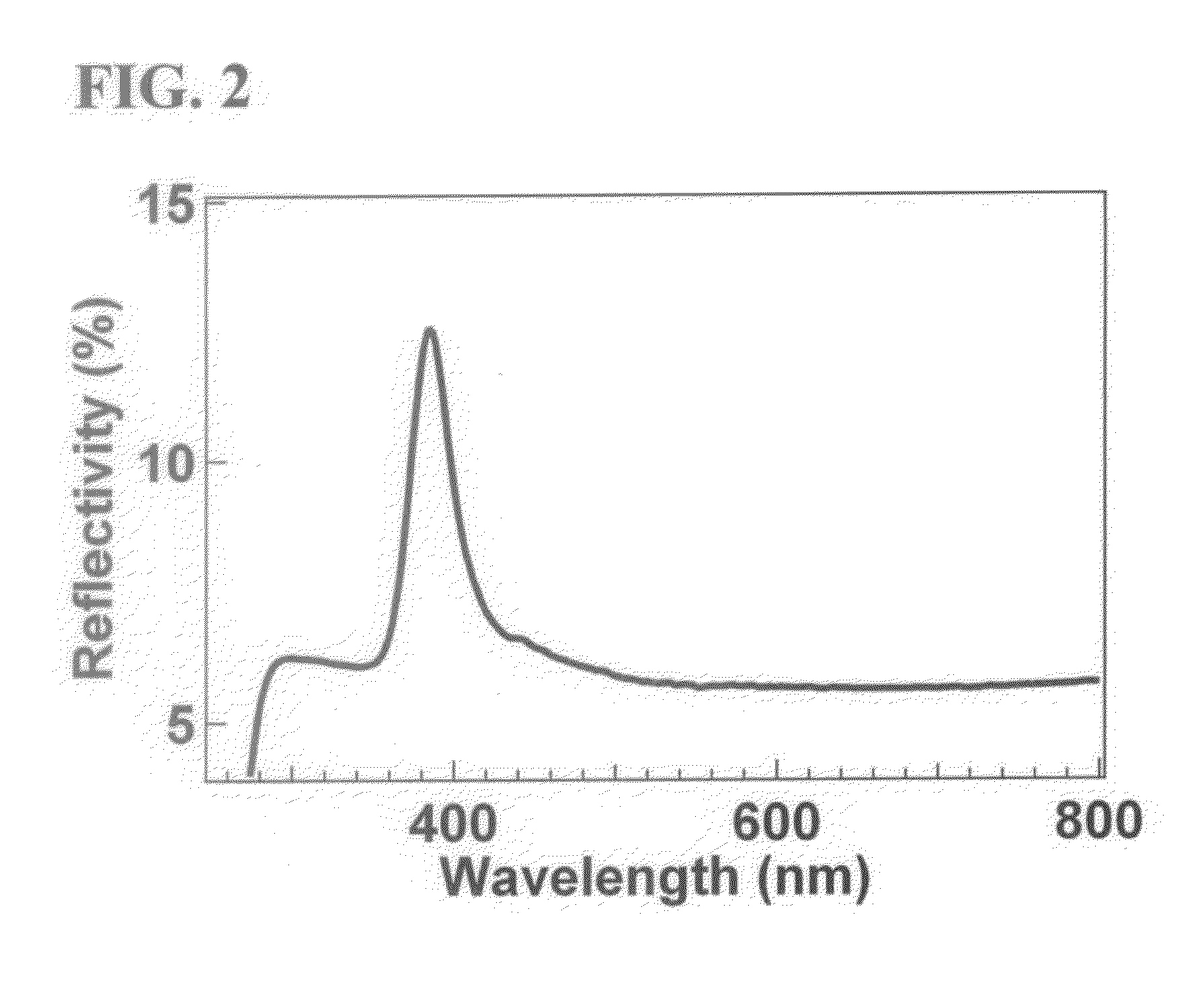
The present invention is related to a non-volatile photonic material that has a nanophase-separated structure made of different polymer chains. One of the polymer chains is swelled with a non-volatile solvent, which results in the material reflecting light rays in a wider wavelength range. This allows the material to reflect a part of light rays in a wavelength region from near-ultraviolet light to near-infrared light. Additionally, the swelled polymer chains are not returned to their unswelled initial state by evaporation of the solvent during storage. This results in the material being able to reflect a part of light rays in this wavelength region over a long time.

Problems solved by technology

Thus, the practical use and production of such a nanostructure have been limited.

Method used


Image

  • Non-volatile photonic material and production method of the same
  • Non-volatile photonic material and production method of the same
  • Non-volatile photonic material and production method of the same

Examples


example 1

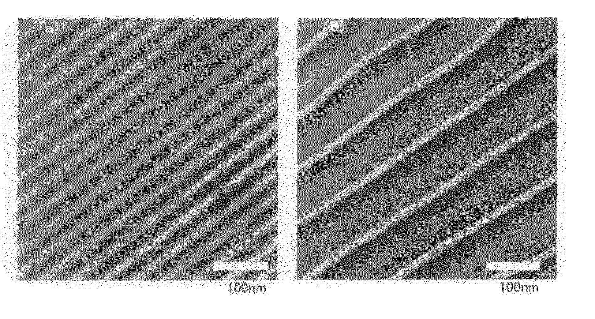
[0051]Polystyrene-b-poly(2-vinylpyridine) (hereinafter referred to as “PS-P2VP”) was synthesized as an AB diblock copolymer with reference to a block copolymer synthesis method (high-vacuum breakable sealing method) disclosed in Polymer Journal 18, pp. 493-499 (1986). A procedure will be shown in detail below.

[0052]The interior of a high-vacuum reactor was washed with a solution of α-styrene tetramer disodium in THF. A THF solution (1.92×10⁻² M, 5.5 mL) of cumyl potassium synthesized by a reaction of cumyl methyl ether and metallic potassium was introduced into the high-vacuum reactor, and then 300 mL of highly purified THF was added. After the reactor was cooled to −78° C. and the content in the reactor was sufficiently stirred, a solution of styrene monomer in THF (1.92 M, 25 mL) was introduced into the reactor, and thus anionic polymerization was started. After 15 minutes, a solution of 2-vinylpyridine monomer in THF (1.92 M, 25 mL) was introduced into the reactor, and thus block...

example 2

[0056]PS-P2VP was synthesized in the same manner as in Example 1, except that a solution of cumyl potassium in THF (1.92×10⁻² M, 4.2 mL) was used. The resulting PS-P2VP was Mw / Mn=1.14, φs=0.47, and Mn=108 k. Thus obtained PS-P2VP is hereinafter referred to as SP02. Using this SP02, a photonic film of Example 2 was produced in the same manner as in Example 1.

example 3

[0057]PS-P2VP was synthesized in the same manner as in Example 1, except that a solution of cumyl potassium in THF (1.92×10⁻² M, 3.2 mL) was used. The resulting PS-P2VP was Mw / Mn=1.06, φs=0.50, and Mn=158 k. Thus obtained PS-P2VP is hereinafter referred to as SP03. Using the SP03, a photonic film of Example 3 was produced in the same manner as in Example 1.


PUM

PropertyMeasurementUnit
Structureaaaaaaaaaa
Sizeaaaaaaaaaa
Wavelengthaaaaaaaaaa

Abstract

A photonic material capable of reflecting part of the light rays in a wavelength region from near-ultraviolet light to near-infrared light. The photonic material contains a block copolymer including a plurality of different polymer chains connected to one another. Each polymer chain independently forms a portion of an aggregated nanophase separated structure. At least one of the plurality of polymer chains is swelled with a non-volatile solvent. An example of such a photonic material may be a polystyrene-b-poly(2-vinylpyridine) block copolymer whose poly(2-vinylpyridine) phase is swelled with an ionic liquid.

Description

TECHNICAL FIELD[0001]The present invention relates to a non-volatile photonic material and a method for producing the same.BACKGROUND ART[0002]It is known that block copolymers made up of different incompatible polymers connected to one another form regular periodic structures in which heterologous domains of several nanometers to several hundreds of nanometers are phase-separated, that is, nanophase-separated structures (may also be referred to as microphase-separated structures or mesophase-separated structures) (NPL 1). On the other hand, a photonic material has a periodic nanostructure made of different components having different refractive indices, and a one-dimensional photonic material having a one-dimensionally repetitive structure reflects light having a specific wavelength. Accordingly, a photonic material can be produced from a block copolymer containing components having different dielectric constants or, in practice, different refractive indices (PTL 1, PTL 2). For for...

Claims


Application Information

Patent Timeline
IPC IPC(8): G02B1/04B05D3/10B05D5/06
CPCG02B1/04B05D3/107B05D5/063C08F297/02C08L53/00G02B1/02C08K5/19C08K5/34
Inventor NORO, ATSUSHITOMITA, YUSUKEMATSUSHIMA, SATORUSAGESHIMA, YOSHIOMATSUSHITA, YUSHUWALISH, JOSEPH J.THOMAS, EDWIN L.
Owner NAGOYA UNIVERSITY
Learn More