
Data transmission system and method jointly using a terrestrial link and a satellite link

a data transmission system and satellite link technology, applied in the field of telecommunications, to achieve the effect of improving the reliability of communications

Inactive Publication Date: 2016-06-23
THALES SA
View PDF9 Cites 4 Cited by
  • Summary
  • Abstract
  • Description
  • Claims
  • Application Information

AI Technical Summary

Benefits of technology

The invention proposes a hybrid telecommunication system that uses both a terrestrial link and a satellite link to improve the reliability of communications. This is achieved through the use of OFDM modulation and turbo-codes on both links, which results in a stronger link budget and increased reliability. The two radio links must be synchronized, and the use of an OFDM modulation allows for a limited time offset between the two links. This system is designed for communications with drones and ensures the reliability and continuity of data link.

Problems solved by technology

The opening up of the non-segregated airspace to drones poses numerous technological problems, such as that of the reliability of the anti-collision mechanisms, or that of the reliability of the telecommunication systems used for control and command.

Method used


Image

  • Data transmission system and method jointly using a terrestrial link and a satellite link
  • Data transmission system and method jointly using a terrestrial link and a satellite link
  • Data transmission system and method jointly using a terrestrial link and a satellite link

Examples


first embodiment

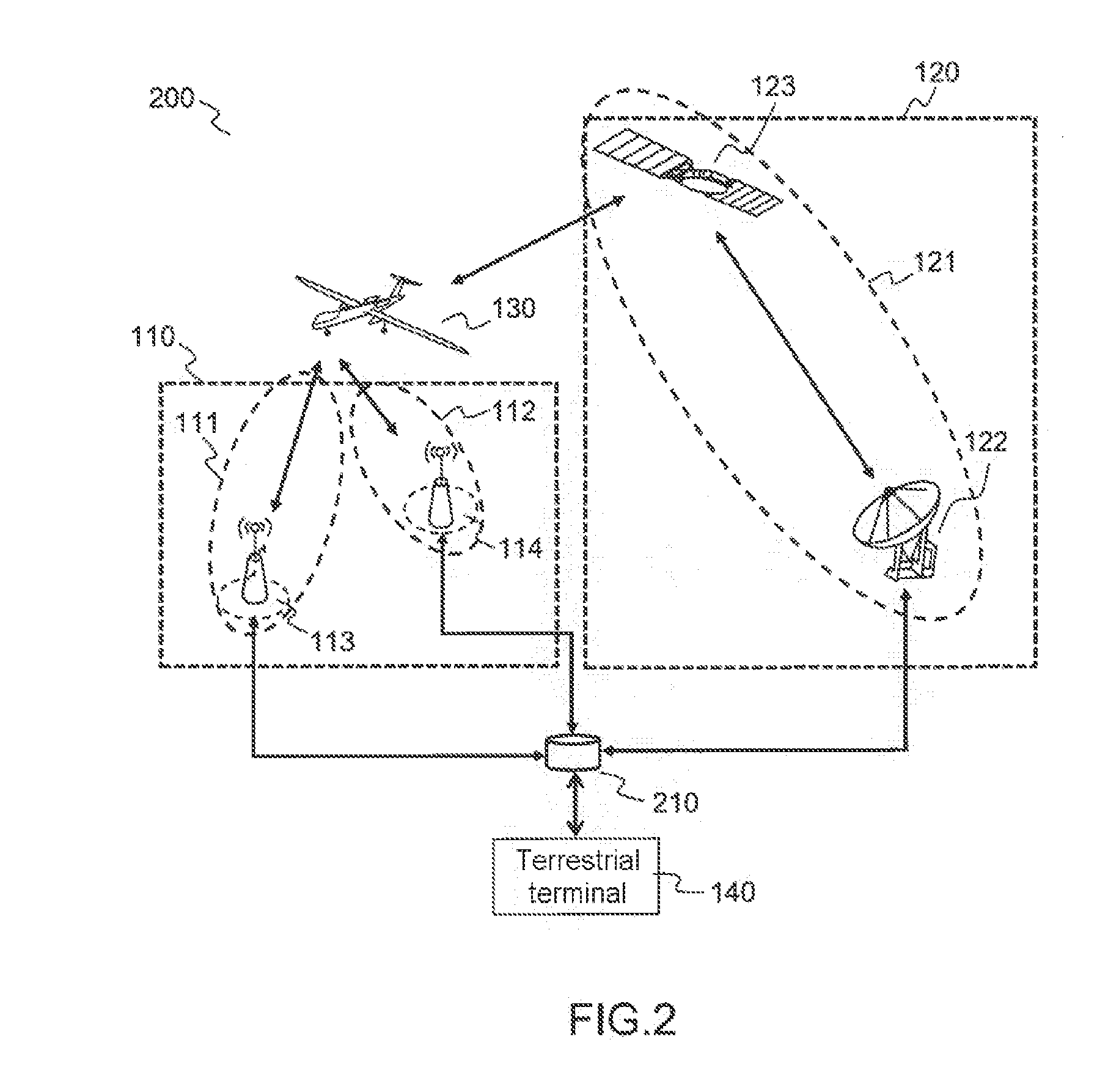
[0084]FIG. 2 illustrates a telecommunication network 200 comprising a number of access networks from and to a mobile terminal 130 according to the invention.

[0085]In this embodiment, the different access gateways 113, 114 and 122 are directly linked to a gateway, called hybridation gateway 210.

[0086]Contrary to the prior art, the hybridation gateway is directly connected to the different access networks and to the mobile terminal 130. It is a single point of access to each of the access networks, and implements, in real time, the functions traditionally specific to each of these access networks.

[0087]The hybridation gateway is linked to each of the access gateways 113, 114 and 121, through point-to-point connections, or IP networks. Each of these links is made by using distinct ports. In this way, the switching from one network to another is done instantaneously from the hybridation station, by switching over the port used to transmit the data. Contrary to the prior art, the switcho...

second embodiment

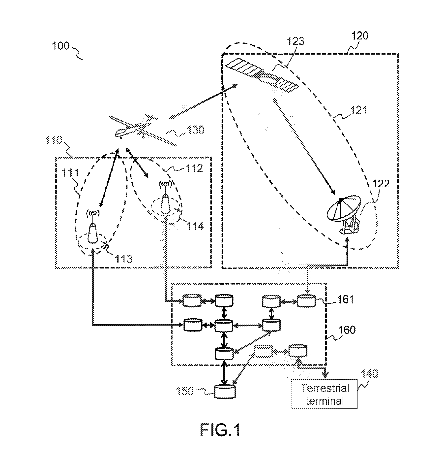
[0105]FIG. 3 illustrates a telecommunication network comprising a number of access networks according to the invention.

[0106]In this case, the telecommunication network 300 has two redundant satellite access networks 310 and 320 available, each including a satellite access gateway 311 and 321.

[0107]In case of failure of the satellite gateway used, the hybridation gateway 210 can instantaneously switch over to the second gateway without loss of context, or of data. Since the physical resources used (such as the frequency for example) are identical, the switchover is performed transparently for the mobile terminal. This mode of operation is particularly useful for the satellite links, for which the availability of the satellites 123 is low, and therefore particularly affected by the losses of packets and retransmissions.

[0108]The second embodiment, illustrated by FIG. 2, and the third embodiment, illustrated by FIG. 3, can be implemented simultaneously in a same telecommunication netw...


PUM


Abstract

A system for bidirectional data transmission in a telecommunication network comprises at least two distinct access networks to a mobile terminal, comprising at least one hybridation gateway that is configured to constitute an access point to each of the access networks, and to perform at least: control functions for all of the access networks, selection functions for the access network or networks selected for the data transmission, network layer functions, and data link layer functions, and wherein each of the access networks comprises at least one access gateway configured to perform at least physical layer functions.

Description

CROSS-REFERENCE TO RELATED APPLICATION[0001]This application claims priority to foreign French patent application No. FR 1402968, filed on Dec. 23, 2014, the disclosure of which is incorporated by reference in its entirety.FIELD OF THE INVENTION[0002]The invention lies in the field of telecommunications, and more particularly in the field of telecommunication systems dedicated to drone control and command.[0003]It aims to propose a system, and the associated method, allowing for the combined and coordinated use of a satellite link and of a terrestrial wireless link in a telecommunication network, for the bidirectional transmission of data.[0004]The invention describes the architecture of a distributed real-time hybrid station allowing for the implementation of such a system.BACKGROUND[0005]The insertion of unmanned aircraft, or drones, into airspace is currently limited to appropriate spaces, called “segregated” spaces, so as to limit the risks of incidents. The segregated spaces ar...

Claims


Application Information

Patent Timeline
Patent Type & Authority Applications(United States)
IPC IPC(8): H04B1/3822H04W88/12H04W88/16H04B7/185H04W88/06
CPCH04B1/3822H04B7/1851H04W88/12H04W88/16H04W88/06H04W88/10H04B7/18504
Inventor RATINEY, MARCVAN WAMBEKE, NICOLASGADAT, BENJAMIN
Owner THALES SA
Learn More