
Tactile Feedback for Joystick Position/Speed Controls

a joystick and position/speed control technology, applied in the direction of manual control with single controlling member, mechanical control device, instruments, etc., can solve the problems of difficult to predict how much further a platform will travel, jerky platform movement, and overshooting the intended position, so as to shorten the training curve, enhance ease of use, and minimize unnecessary cost and complexity

Active Publication Date: 2016-06-23
ENOVATION CONTROLS
View PDF3 Cites 44 Cited by
  • Summary
  • Abstract
  • Description
  • Claims
  • Application Information

AI Technical Summary

Benefits of technology

The present invention provides a solution for the unmet needs in the prior art by allowing for precise and smooth speed control with touch feedback that is intuitively understood and adjusted by the user. The invention can be applied to joystick controllers, which are commonly used to control the operation of powered implements. The invention provides a way for the operator of the joystick to have a tactile experience and understand the current speed of the implement being controlled. This haptic feedback can include vibrations or other forms that alert the operator to various operational conditions of the implement, such as when it is approaching its mechanical limits or when it is in a dangerous condition. The invention also allows for active influence on the speed of the subject when the joystick is forced to a position outside of its actual-speed-biased position. Overall, the invention provides a more reliable and intuitive way to control the operation of joystick controllers and powered implements.

Problems solved by technology

Overshooting the intended position can be hazardous, particularly when that position is close to a structure that can be damaged if impacted by the boom-lift platform.
Without sophisticated controls that are common today, platform movements can be very jerky.
On the other hand, because of the great effort to smooth out the movements of aerial platforms, it is very difficult to predict how much further a platform will travel before stopping once the joystick controller is released to the neutral position.
The slow, gradual approach with fine movement control can be extremely time-consuming.

Method used


Image

  • Tactile Feedback for Joystick Position/Speed Controls
  • Tactile Feedback for Joystick Position/Speed Controls
  • Tactile Feedback for Joystick Position/Speed Controls

Examples


Embodiment Construction

The Larger Contexts.

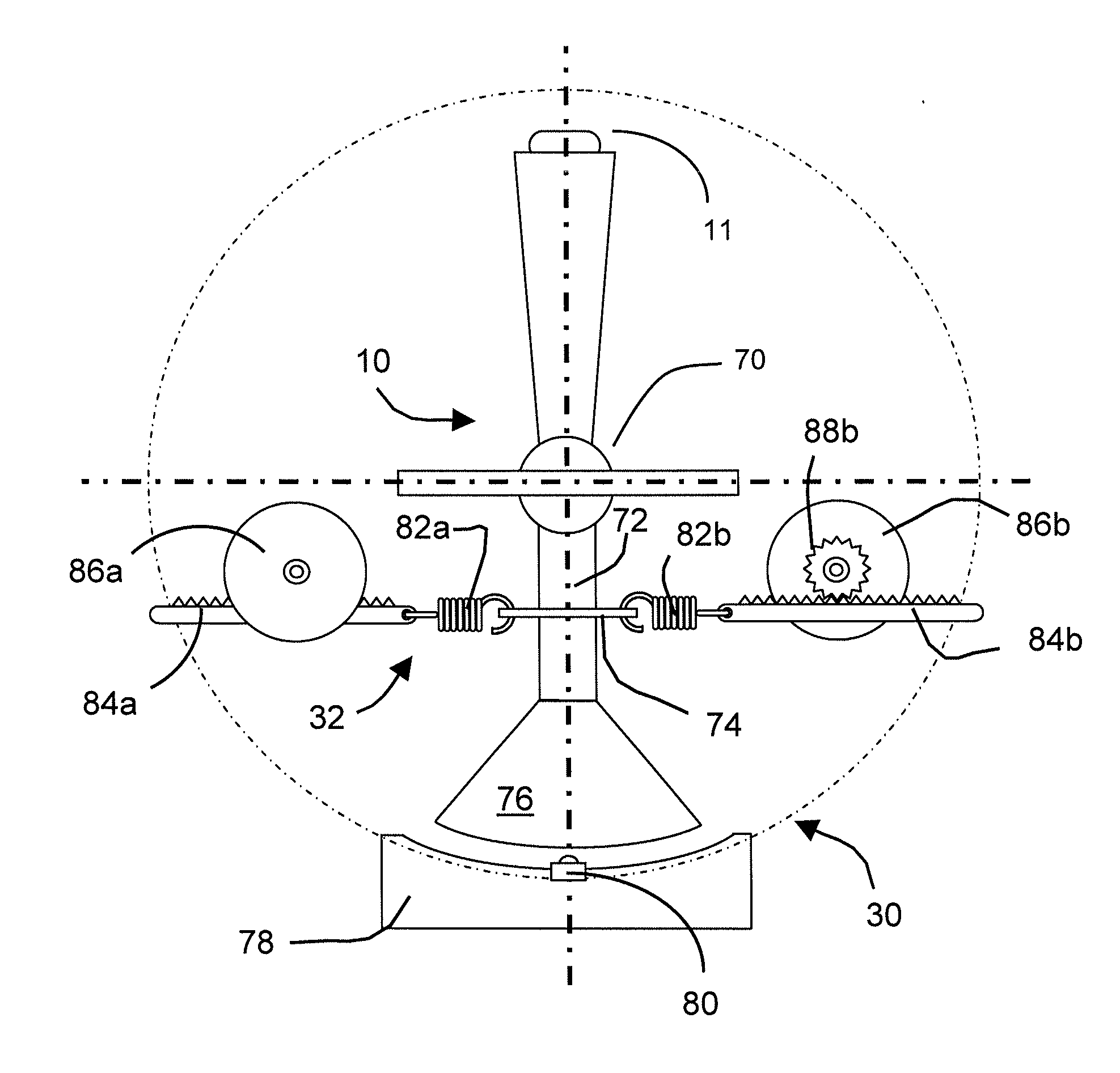
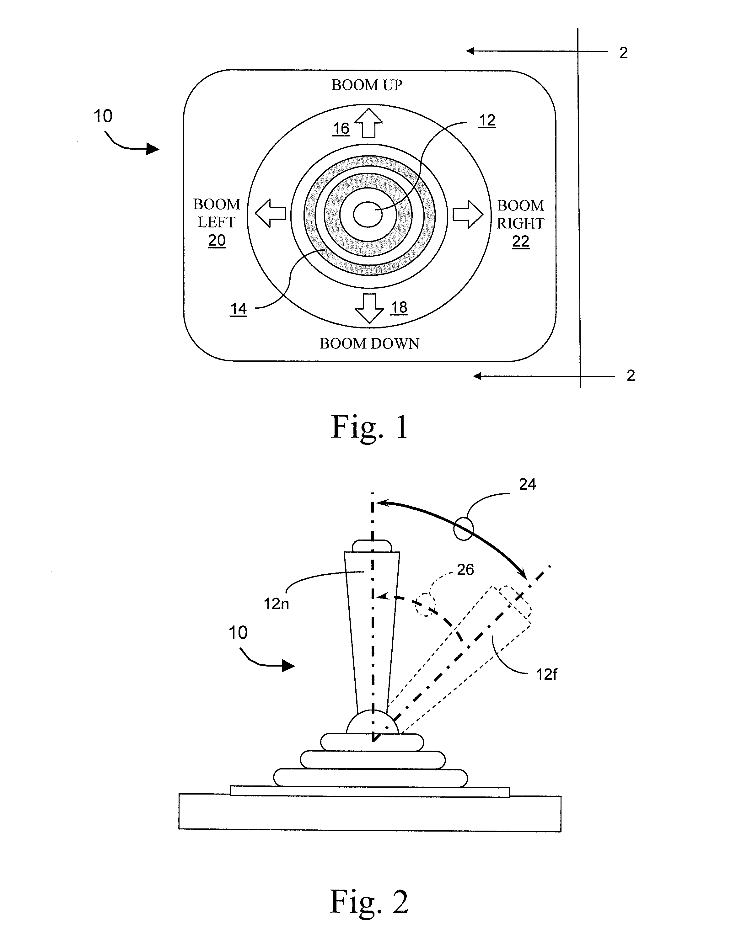
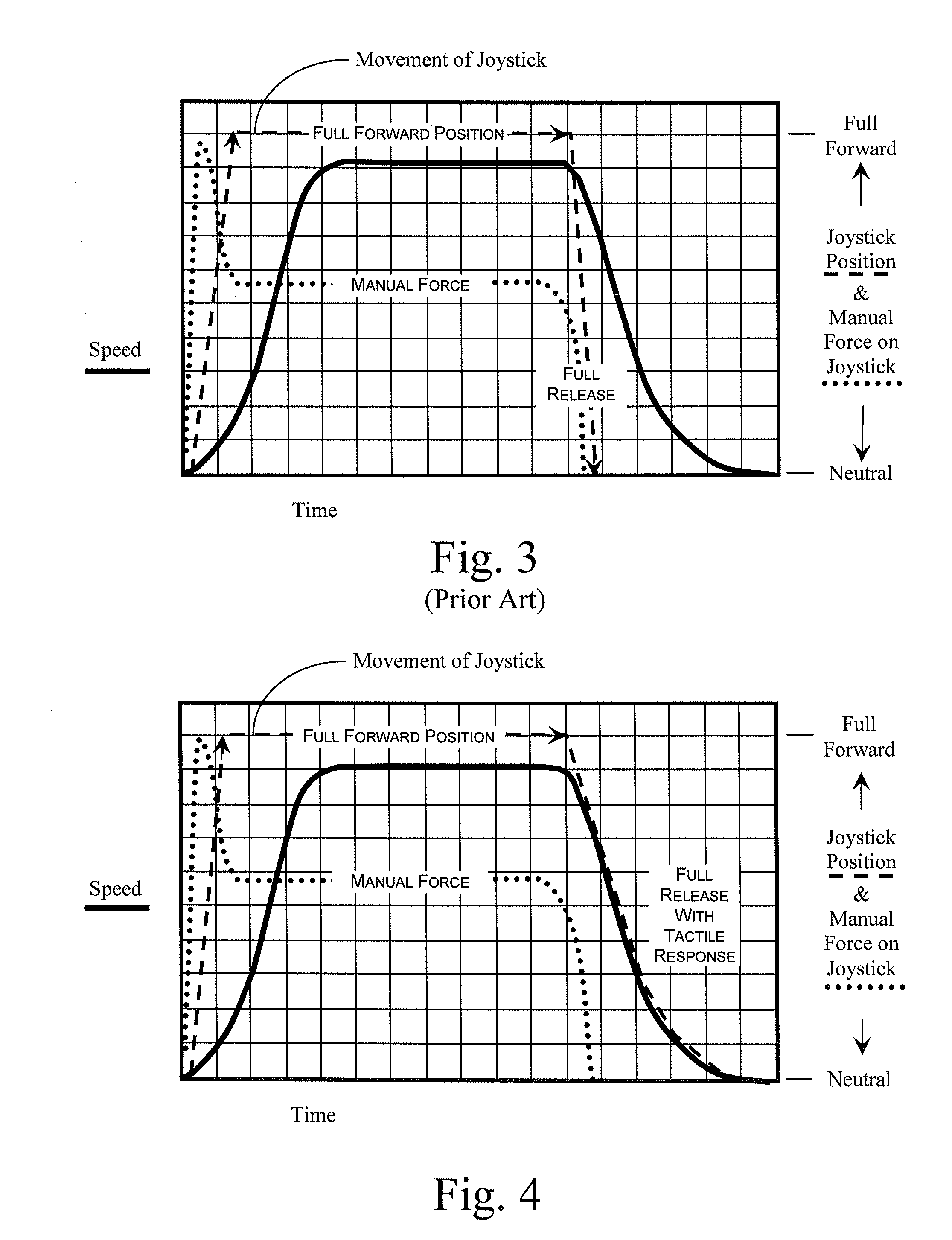
[0029]While the inventions that are the subject of this application are much more basic than any particular embodiment, one can gather a partial appreciation for some of the possible benefits of the broader inventions and possible interplay between various elements of the inventions in the course of considering presently preferred embodiments. A few embodiments that are presently thought to include the most preferred are depicted in relation to FIGS. 1-11 of the drawings, where similar reference numerals are used for similar elements of various embodiments. The systems and methods depicted therein allow for efficient and effective speed control that provides intuitive tactile feedback to the operator, together with related measures for controlling the motion of an intended subject.

[0030]The present invention finds application in any of a number of control system environments where a level of responsive feedback is desired with the user manipulation of joystick-ty...


PUM


Abstract

A joystick controller is disclosed for controlling movement of a boom lift platform, the controller having actuators or the like that provide one or more forms of tactile feedback that are intuitively interpreted and adjusted by the user of the joystick motion control, the joystick being neutrally-biased to effect a null movement when the joystick is positioned in a neutral position, but also being adapted with at least one form of tactile feedback by which the joystick controller conveys information about the boom lift's operation to the joystick operator, such as through resistive force or through vibrations or the like.

Description

CLAIM OF PRIORITY TO PRIOR APPLICATION[0001]This application claims the benefit of the filing date and is a continuation-in-part of U.S. Non-Provisional application Ser. No. 14 / 275,088, filed on May 12, 2014, which is a continuation of U.S. Non-Provisional application Ser. No. 13 / 846,177, filed on Mar. 18, 2013, which is a continuation of U.S. Non-Provisional application Ser. No. 12 / 773,170, filed on May 4, 2010, which claims the benefit of the filing date of U.S. Provisional Application, Ser. No. 61 / 217,552, filed on Jun. 1, 2009, entitled “Tactile Feedback for Joystick Position / Speed Controls,” the entire disclosures of which are hereby incorporated by reference into the present disclosure.BACKGROUND OF THE INVENTION[0002]1. Technical Field[0003]Many aspects of this invention relate in general to proportional joystick speed controls for powered implements and, more particularly, to comprehensive systems and methods for providing an operator with feedback related to the actual spee...

Claims


Application Information

Patent Timeline
Patent Type & Authority Applications(United States)
IPC IPC(8): G05G9/06B66F17/00B66F11/04B62D1/12G05G1/04
CPCG05G9/06B62D1/12B66F17/006B66F11/046G05G1/04B66F11/04G05G9/047G05G2009/04766H01H2003/008Y10T74/20201G06F3/016G06F3/0338G06F2203/015G05G2009/0477G05G2009/04777
Inventor GUGLIELMO, KENNON
Owner ENOVATION CONTROLS
Learn More