
Compiler for and method for software defined networks

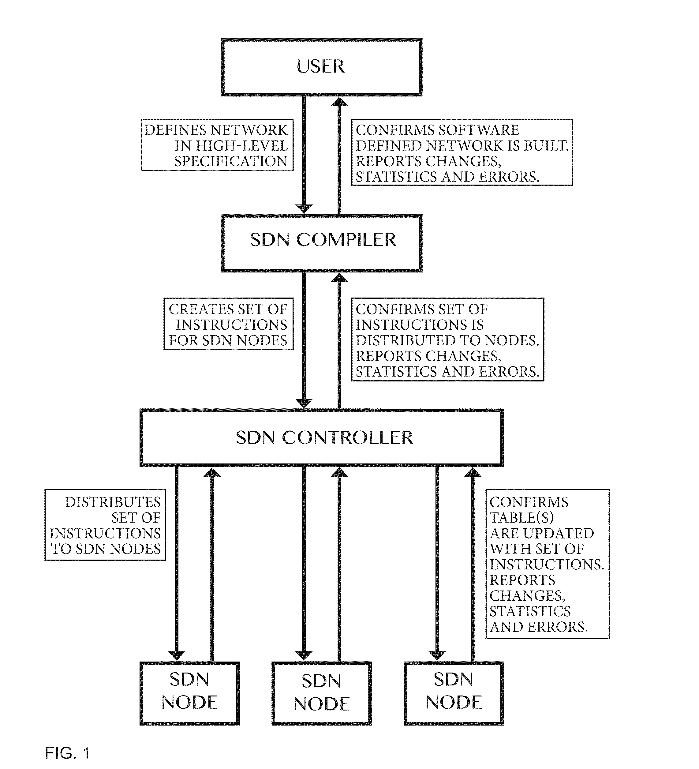
a software defined network and compiler technology, applied in the field of communication networks and computing equipment, can solve the problems of placing a requirement on physical nodes, affecting the operation of virtual overlay networks and underlay networks, and affecting the operation of network elements based on network services, so as to achieve less complex forwarding hardware and software forwarding implementations, speed up computation processes, and reasonable size of forwarding tables

Active Publication Date: 2016-06-16
WOLTING HLDG
View PDF4 Cites 224 Cited by
  • Summary
  • Abstract
  • Description
  • Claims
  • Application Information

AI Technical Summary

Benefits of technology

The patent describes a method for improving the speed and efficiency of computing in network devices by using a hierarchical naming structure and parallel computation. This method can be applied to various protocols and network identifiers, and simplifies the process of specifying, implementing, and maintaining complex network services. Additionally, the method allows for the use of IPv4 and IPv6 naming, and does not require any conversion in physical nodes or an underlay network. Overall, the described invention provides a more efficient and flexible way to manage network traffic.

Problems solved by technology

), having the disadvantage of placing a requirement on physical nodes to perform this conversion and using resources in said physical nodes.
This approach has the disadvantage of operating both the virtual overlay network and the underlay network complicating operations.
Moreover, the prior art according to US2013 / 044641 models a virtual node, in terminology of this application a logical node, after a physical node, having the disadvantage of continuing to configure and manage networks based on network element operations rather than network services.

Method used


Image

  • Compiler for and method for software defined networks
  • Compiler for and method for software defined networks
  • Compiler for and method for software defined networks

Examples


case b

[1125) Network KKK is a CSN and network KGG is a PSN. Note that therefore network LKK is a CSN and network LGG is a PSN. In FIG. 40B channel identifiers C1 through C8 are shown. Channel identifier ‘C1’ is used for the topology-mapping from network KK to network KL. Channel identifier ‘C2’ is used for the topology-mapping from network KL to network KM. Channel identifier ‘C3’ is used for the topology-mapping from network KM to network KN. Channel identifier ‘C4’ is used for the topology-mapping from network KN to network KP. Channel identifier ‘C5’ is used for the topology-mapping from network KP to network KQ. Channel identifier ‘C6’ is used for the topology-mapping from network KQ to network KR. Channel identifier ‘C7’ is used for the topology-mapping from network KR to network KS. Channel identifier ‘C8’ is used for the topology-mapping from network KS to network KT. The address of source node LG is LGG.LG and the address of destination node LJ is LGG.LJ.

[1126]The forwarding instr...


PUM


Abstract

Method of and a compiler for controlling a network based on a logical network model. The network has physical nodes and virtual nodes. The physical nodes are interconnected by physical links in accordance with a physical network layout. The logical network model has logical nodes indicated with a logical node name which refers to at least one physical or at least one virtual node in the network. The method uses a physical forwarding point-of-attachment relation defining physical paths of the physical network in dependence on a physical forwarding policy, a first mapping relation defining how the virtual nodes and the physical nodes are mapped to one another, and a second mapping relation defining how the logical nodes are mapped to the physical nodes and the virtual nodes. The method also includes transforming paths in the physical network to paths between the physical nodes and the virtual nodes.

Description

TECHNICAL FIELD[0001]The present invention relates to communication networks and computing equipment. Such networks may be packet switched. In particular, the present invention relates to a method for configuring packet forwarding devices, computing equipment, virtual switches and virtual machines in physical and virtual networks.BACKGROUND INFORMATION[0002]Recent developments in the field of Packet Switched Networking (PSN) and Computing have lead to the notion of Software Defined Networking (SDN). Within the context of this invention we consider Software Defined Networking as the capability to define a network in a high-level specification (such as, but not limited to, a high-level programming or scripting language) and through an automated process instruct the appropriate physical and virtual networking and computing resources in accordance with this specification.[0003]Such recent developments can be found in WO2010115060 “Method and apparatus for implementing and managing virtu...

Claims


Application Information

Patent Timeline
Patent Type & Authority Applications(United States)
IPC IPC(8): H04L12/24H04L29/08H04L12/741H04L45/42H04L45/586H04L45/74
CPCH04L41/12H04L67/1097H04L45/74H04L41/145H04L45/586H04L45/64H04L45/123H04L41/40H04L41/342H04L41/122
Inventor WOLTING, SIMON
Owner WOLTING HLDG
Learn More