
Electrical connecting module

Inactive Publication Date: 2016-06-16
DAIICHI SEIKO CO LTD
View PDF2 Cites 11 Cited by
  • Summary
  • Abstract
  • Description
  • Claims
  • Application Information

AI Technical Summary

Benefits of technology

The present invention provides an electrical connecting module that allows a contact terminal to connect with a cylindrical terminal without being damaged or deformed. This enhances the reliability of the electrical connection between the contact terminal and the cylindrical terminal. The module includes an elastic contact piece that can contact the cylindrical terminal even when the first and second housings are positioned relative to each other. This prevents the elastic contact piece from scratching or wearing down the cylindrical terminal due to mutual rotation of the housings. The elastic contact piece can contact the cylindrical terminal at the inner surface, ensuring reliable connection between the contact terminal and the cylindrical terminal.

Problems solved by technology

Accordingly, the contact terminal may be scratched or damaged by the step / steps when the first and second housings are fit into each other.
Furthermore, if one of the first and second electrical connectors rotates around an axis thereof due to oscillation and / or impact while the first and second electrical connectors are being fit into each other, the contact terminal slides on the above-mentioned area, resulting in that the contact terminal may be worn out and / or deformed.
Thus, it is afraid that there occurs defectiveness in electrical connection between the first and second electrical connectors.

Method used


Image

  • Electrical connecting module
  • Electrical connecting module
  • Electrical connecting module

Examples


Embodiment Construction

[0068]A connector terminal according to the first embodiment of the present invention will be explained hereinbelow with reference to drawings.

[0069]In the specification, with respect to words of “front and rear,” a word of “front” means a side through which the two electrical connectors are fit into each other, and a word of “rear” means the opposite side of the “front”.

[0070]A first electrical connector 10 illustrated in FIG. 1 and a second electrical connector 20 illustrated in FIG. 10 can be used for connecting various kinds of sensors with a wire harness, for example. The second electrical connector 20 is the connector terminal according to the present invention.

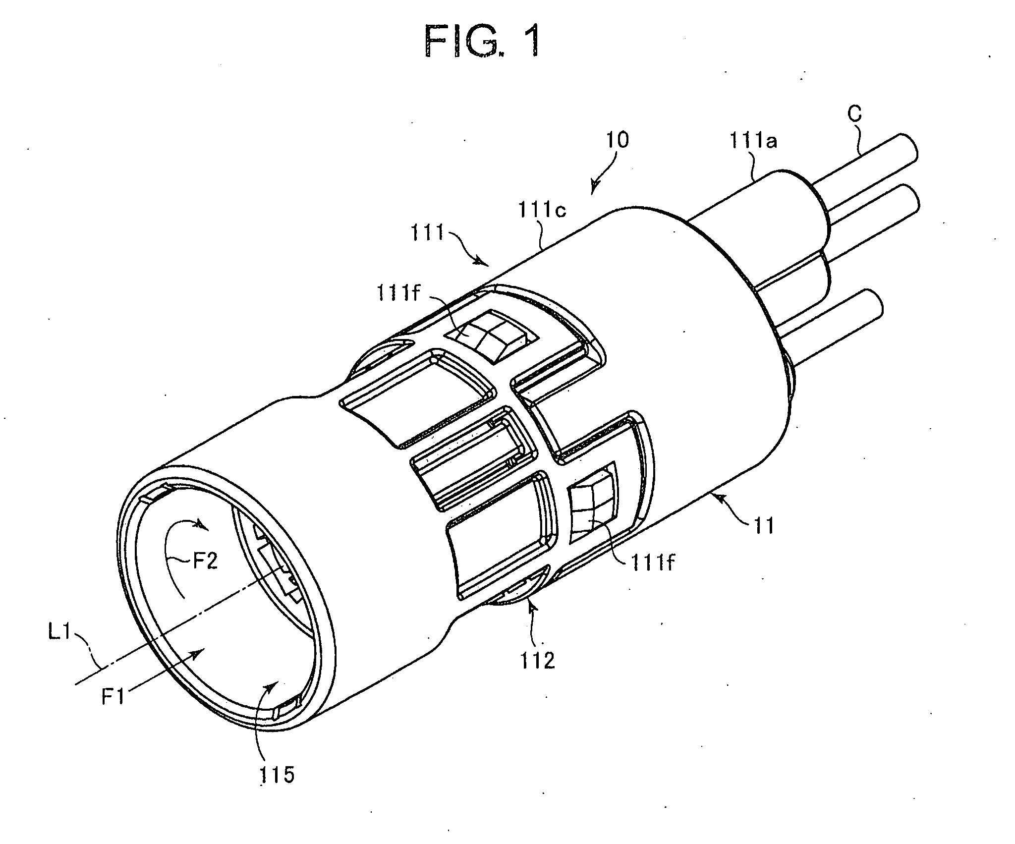
[0071]First, the first electrical connector 10 is explained hereinbelow with reference to FIGS. 1 to 9.

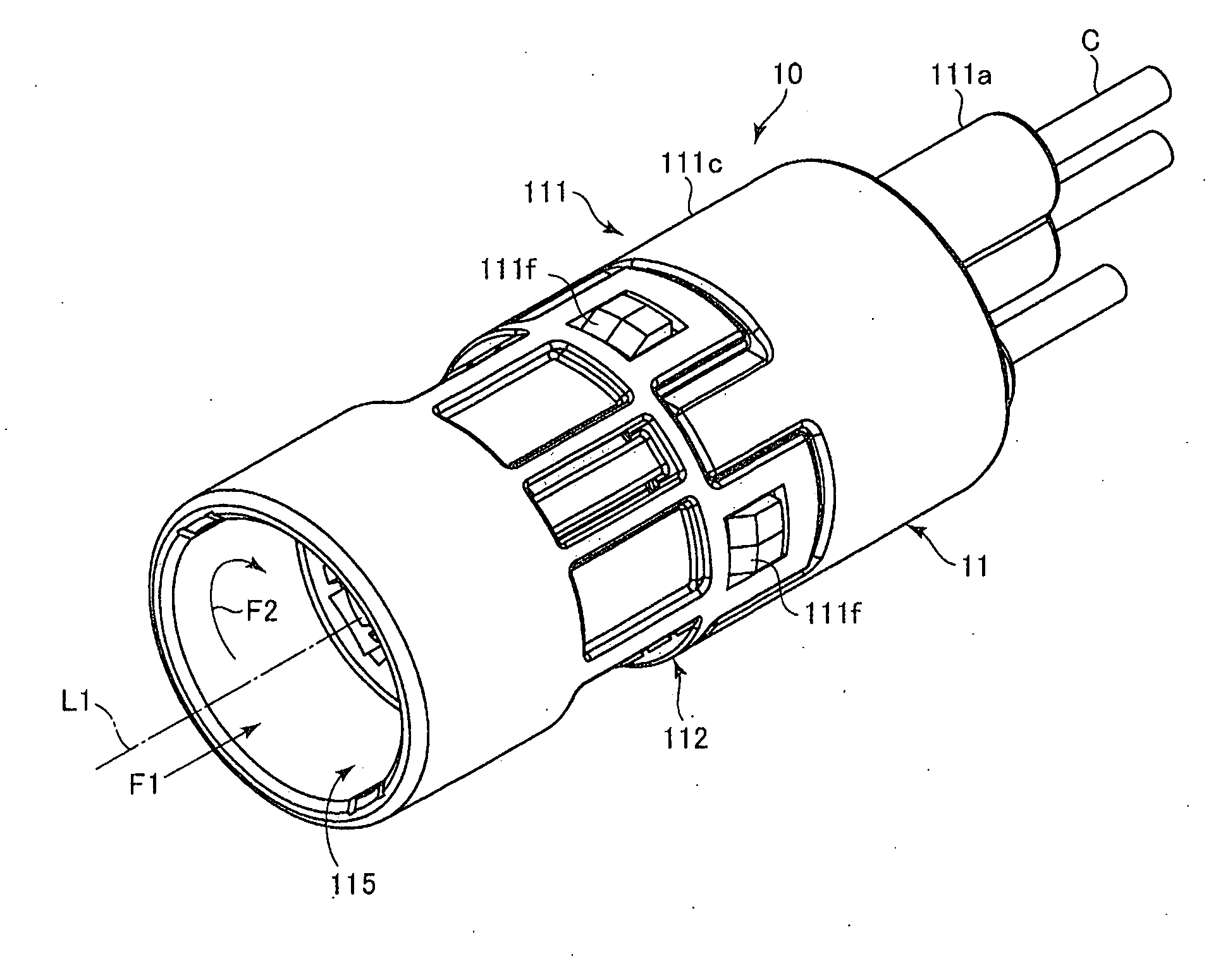
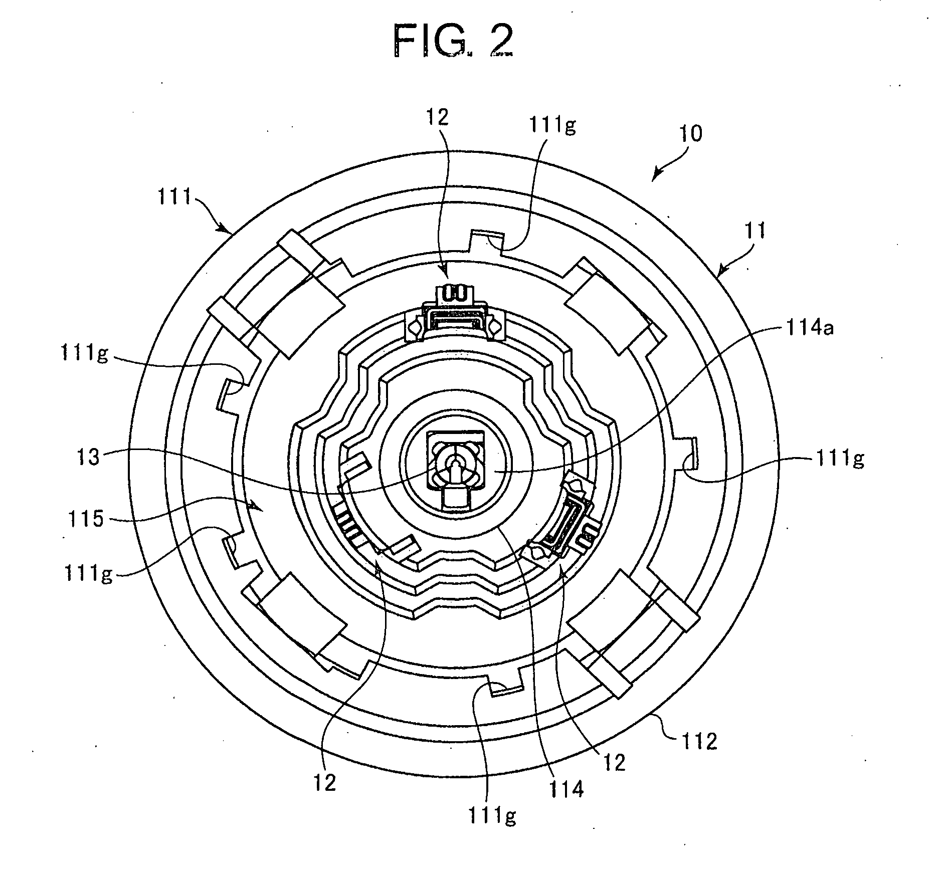
[0072]As illustrated in FIGS. 1, 2 and 14, the first electrical connector 10 includes: an outer housing 11 (a first housing) into which the second electrical connector 20 illustrated in FIG. 10 is fit; a plurality of f...


PUM


Abstract

An electrical connecting module includes a first electrical connector, and a second electrical connector, both being coaxially fittable into each other. The first electrical connector includes a first housing, and a contact terminal housed in a terminal space formed in the first housing. The second electrical connector includes a second housing and a cylindrical terminal fixed in the second housing, the cylindrical terminal being fabricated by joining opposite ends of an electrically conductive sheet to each other in a manner such that the sheet defines a circular cross-section. The contact terminal includes an elastic contact piece contacting an inner surface of the cylindrical terminal. Each of the housings includes a positioning section for causing the elastic contact piece to contact the cylindrical terminal at the inner surface other than an area through which the opposite ends of the electrically conductive sheet are joined to each other.

Description

BACKGROUND OF THE INVENTION[0001]1. Field of the Invention[0002]The present invention relates to an electrical connecting module including: a first electrical connector having a first housing; and a second electrical connector having a second housing, the first and second housing being fit into each other to thereby cause a cylindrical terminal fixed to the first housing and a contact terminal housed in a terminal space formed in the second housing to contact each other.[0003]2. Description of the Related Art[0004]A kind of electrical connector (such as a connector to be equipped in a glow plug acting as an ignitor or a pre-heating plug in an engine, and a connector used for connecting a combustion pressure sensor to a wire harness) generally includes a cylindrical male connector. Since the male connector is designed to be rotation-symmetric with a female connector, the male connector can be fit into the female connector, even if the male connector is caused to rotate around an axis...

Claims


Application Information

Patent Timeline
IPC IPC(8): H01R13/428
CPCH01R13/428H01R13/245H01R13/46H01R24/00H01R13/052H01R13/631H01R13/64H01R24/38
Inventor ENDO, TAKAYOSHIYAGI, SAKAITOUNO, SHUJI
Owner DAIICHI SEIKO CO LTD
Learn More