Slit-type scraper device

Active Publication Date: 2016-06-09
METAL INDS RES & DEV CENT
View PDF0 Cites 12 Cited by
  • Summary
  • Abstract
  • Description
  • Claims
  • Application Information

AI Technical Summary

Benefits of technology

The present invention is a slit-type scraper device that combines an ink storage space and a scraper, using air pressure to assist power for pushing printing ink. This device allows printing ink to be outputted through an ink output slit, achieving the effect of direct ink supplying and preventing the printing ink from directly contacting with the air. Additionally, a gap of the ink output slit has an excellent effect when printing fine circuit patterns. The scraper is designed in an arc shape, ensuring complete coverage of the screen cloth and stable printing. The invention also has an ink storage groove design that isolates the air to prevent the printing ink from volatilizing and accelerates the solvent evaporation. Overall, this device provides a direct and efficient means for printing ink.

Problems solved by technology

However, the conventional scraper technology has the following problems: the printing pressing is difficult to control, and printing parameters, such as a scraper angle, a scraping speed, and a pitch, always need to be adjusted due to different printing ink viscosity, different screen cloth density and different printing resolution, Another problem is an unstable attack angle, and when a printing condition requires increased press amount, a soft squeegee will deform, and because a part of pressure is absorbed by the deformation of the squeegee, the attack angle is affected, so that the printing is even more unstable, Finally, when applying a solvent type printing ink, an area of the printing ink in contact with the air is increased, which accelerates volatilization of a solvent of the printing ink, so that the printing ink becomes more viscous and more difficult in printing.

Method used


Image

  • Slit-type scraper device
  • Slit-type scraper device
  • Slit-type scraper device

Examples


Embodiment Construction

[0022]In order to make the above and other objectives, features and advantages of the present invention clearer, the present invention is described in detail below through the accompanying drawings,

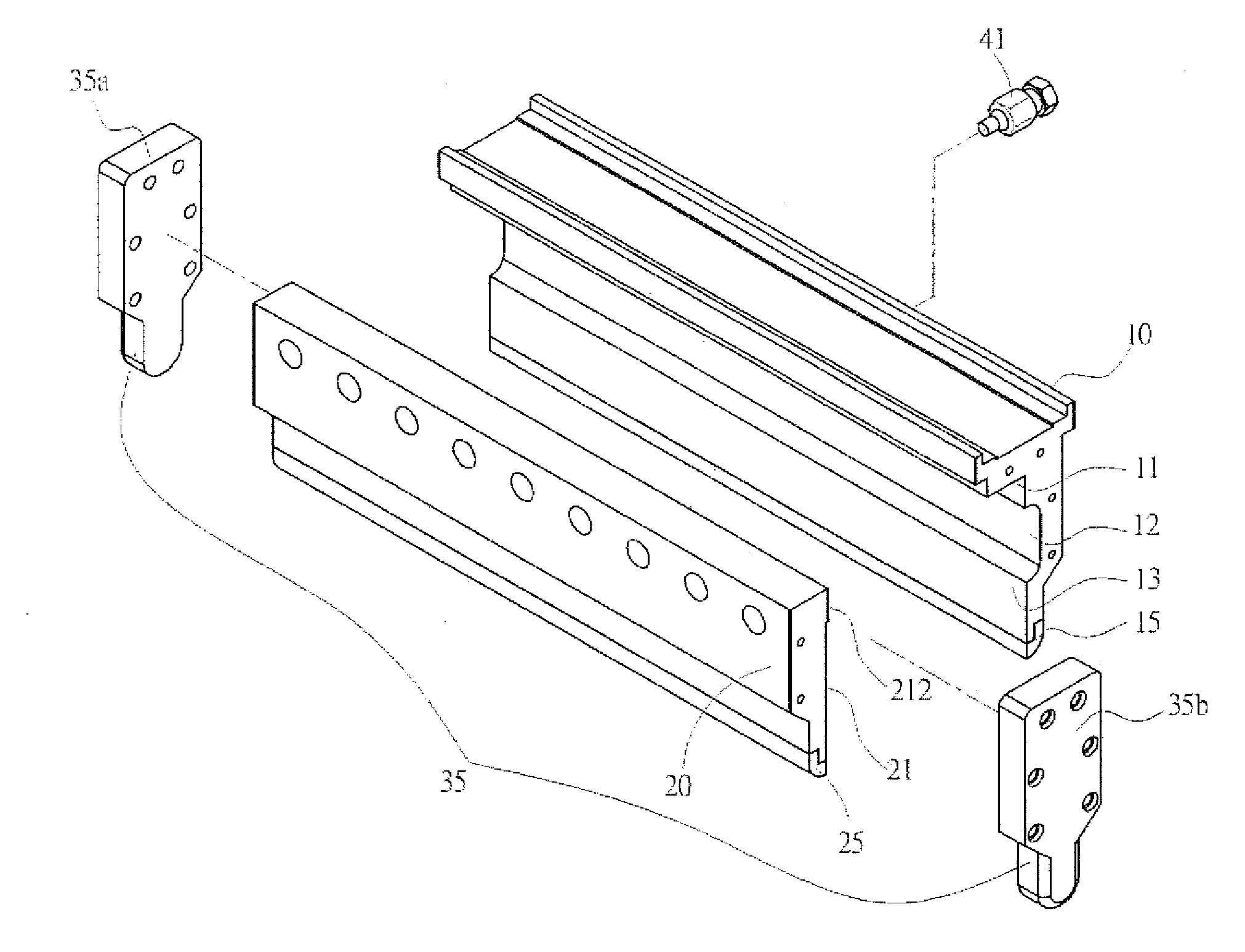
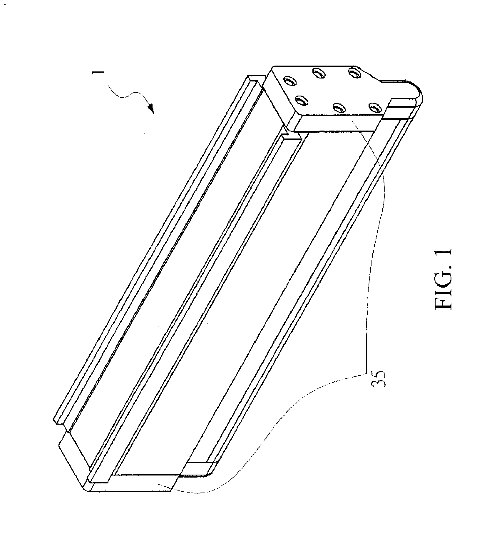
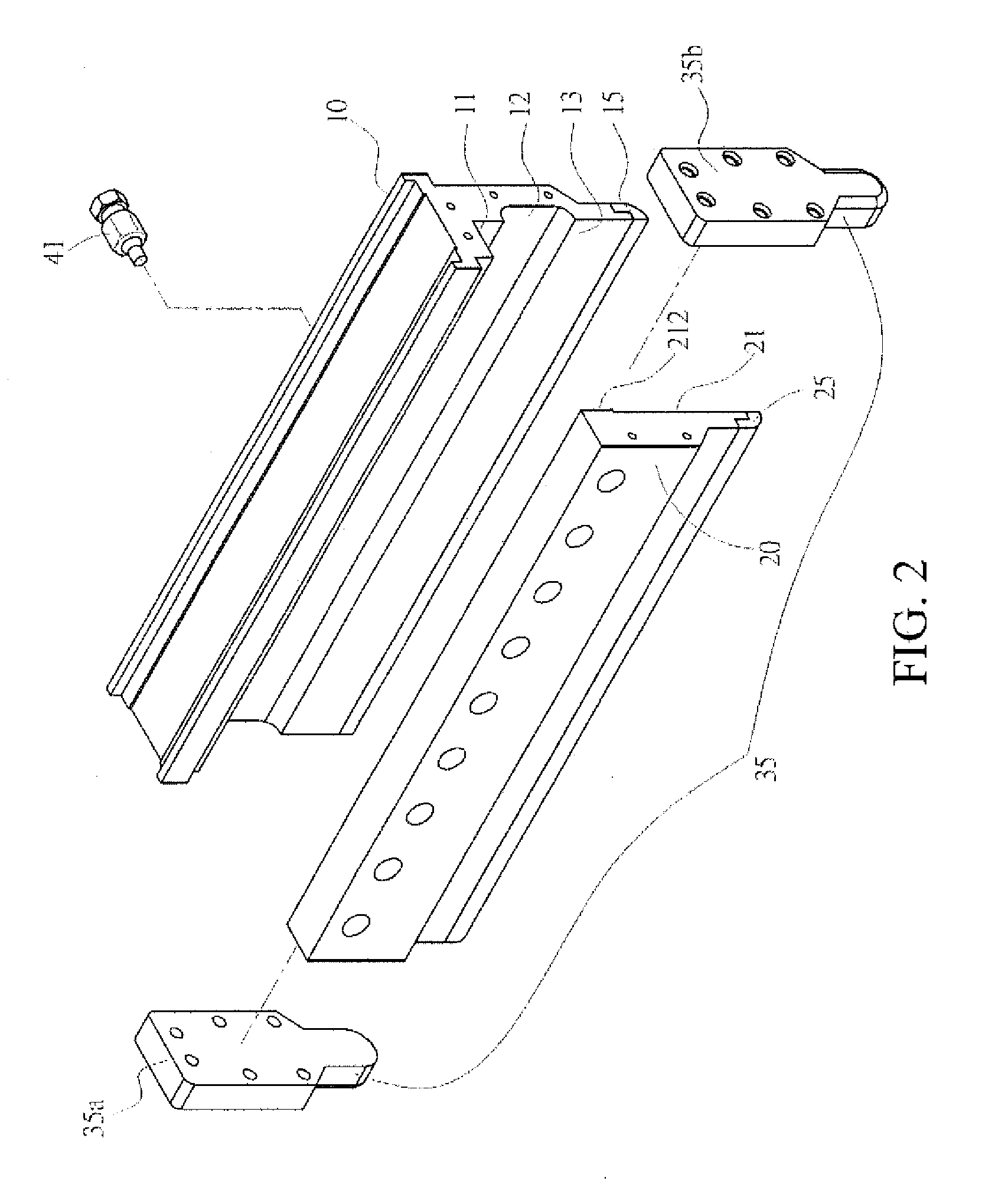
[0023]FIG. 1 is a schematic three-dimensional combination view of a slit-type scraper device according to an embodiment of the present invention, FIG. 2 is a schematic three-dimensional exploded view of a slit extruding-type scraper device according to an embodiment of the present invention, FIG. 3 is a schematic three-dimensional view of combining a body and a cover according to an embodiment of the present invention, and FIG. 4 is a schematic sectional view of a slit extruding-type scraper device according to an embodiment of the present invention, A slit-type scraper device 1 of the present invention is applicable to screen printing 70, but is not limited thereto. Referring to FIG. 1 to FIG. 4, the slit-type scraper device 1 includes: a body 10 and a cover 20. An inner side of the body...


PUM


Abstract

A slit-type scraper device includes: a body, a first scraper portion, a cover, a second scraper portion, an air pressure through hole and a side cover unit. The body includes a groove and a slit portion abutting against the groove. The first scraper portion is abutting against the slit portion. The cover includes a plate portion. The second scraper portion is abutting against the plate portion, wherein the position of the second scraper portion is corresponding to the first scraper portion. The air pressure through hole is disposed on the body, in communication with the groove, and adapted to connect an air pressure connection member to input air pressure. The side cover unit is adapted to form an ink storage space between the plate portion and the groove, and form an ink output slit between the slit portion and the plate portion.

Description

CROSS-REFERENCE TO RELATED APPLICATION[0001]This application claims the benefit of Taiwan Patent Application No. 103142402, filed on Dec. 5, 2014, which is hereby incorporated by reference for all purposes as if fully set forth herein,BACKGROUND[0002]1. Technical Field[0003]The present invention relates to a scraper device, and in particular, to a slit-type scraper device, which combines an ink storage space and a scraper, and uses air pressure to assist power for pushing printing ink, so that the printing ink can be outputted through an ink output slit, thereby achieving the effect of direct ink supplying.[0004]2. Related Art[0005]Currently, environmental protection and portability have been increasingly emphasized, and reducing use of papers is a common object of preventing global warming. In recent years, electronic industries apply many printing technologies to manufacture electronic products, for example, manufacturing electronic elements by printing, printing circuits on a cir...

Claims


Application Information

Patent Timeline
IPC IPC(8): B41F15/44
CPCB41F15/44B41F15/46B41F15/42H05K2203/0126B23K3/06B41F15/40H05K3/1233
Inventor LIU, KUAN-CHIHLIN, CHORNG-TYANFU, HO-CHUNG
Owner METAL INDS RES & DEV CENT
Why Eureka
Try Eureka