
Device and methods for self-centering a guide catheter

a guide catheter and self-centering technology, which is applied in the direction of catheters, guide wires, heart valves, etc., can solve the problems of reduced cardiac output and impairment of heart function, severe shortness of breath, and difficulty in breathing, so as to reduce radiation exposure for patients and physicians, save time and expense, and reduce the risk of thromboembolic stroke

Active Publication Date: 2016-06-09
MAYO FOUND FOR MEDICAL EDUCATION & RES
View PDF6 Cites 22 Cited by
  • Summary
  • Abstract
  • Description
  • Claims
  • Application Information

AI Technical Summary

Benefits of technology

The patent provides devices and methods for quickly aligning a guide catheter with a valve orifice to reduce the risk of complications during cardiac catheterization procedures. This can save time and reduce risks and expenses for patients and physicians. The devices can also be used for TAVR procedures and diagnostic investigations to measure a pressure gradient in aortic stenosis cases. Additionally, the devices have applications for perivalvular mitral valve leaks and fistulas where there is a need to find a fluid flow and to cross against the fluid flow. Non-medical applications include directing closure devices across holes or channels in equipment such as boats and vessels.

Problems solved by technology

However, when the valves can become severely stenotic, that can lead to a reduction in cardiac output and impairment of heart function.
Blood and fluid may then collect in the lung tissue (pulmonary edema), making it hard to breathe.
Mitral valve stenosis can make a person severely short of breath, among other problems.
When the aortic valve is so obstructed, the heart has to work harder to pump blood to the body.
Eventually, this extra work limits the amount of blood the heart can pump, and may weaken the heart muscle.
The left atrium may enlarge as pressure builds up, and blood and fluid may then collect in the lung tissue (pulmonary edema), making it hard to breathe.
One of the most challenging steps when performing a TAVR, valvuloplasty, or hemodynamic study on a stenotic aortic valve is to find the valve orifice and pass a guidewire, catheter, or other elongate medical device through this severely stenotic valve.
The high-pressure jet of blood coming out of the narrowed valve makes it even more challenging to align a catheter and advance against the direction of flow.
Prolonged probing increases the risk or dislodging small amounts of calcified debris and atheroma from the valve surface and can lead to strokes.

Method used


Image

  • Device and methods for self-centering a guide catheter
  • Device and methods for self-centering a guide catheter
  • Device and methods for self-centering a guide catheter

Examples


Embodiment Construction

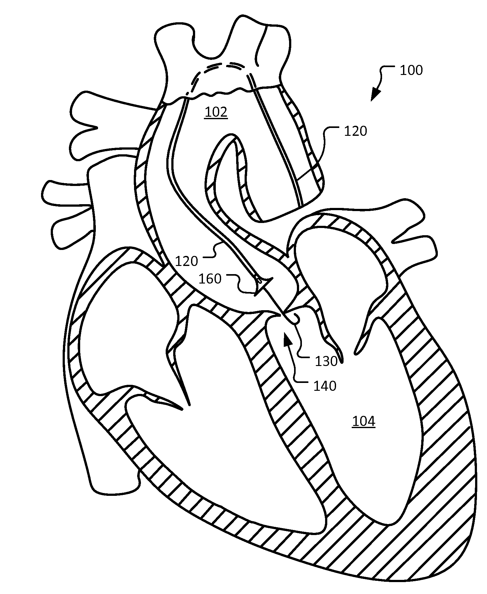
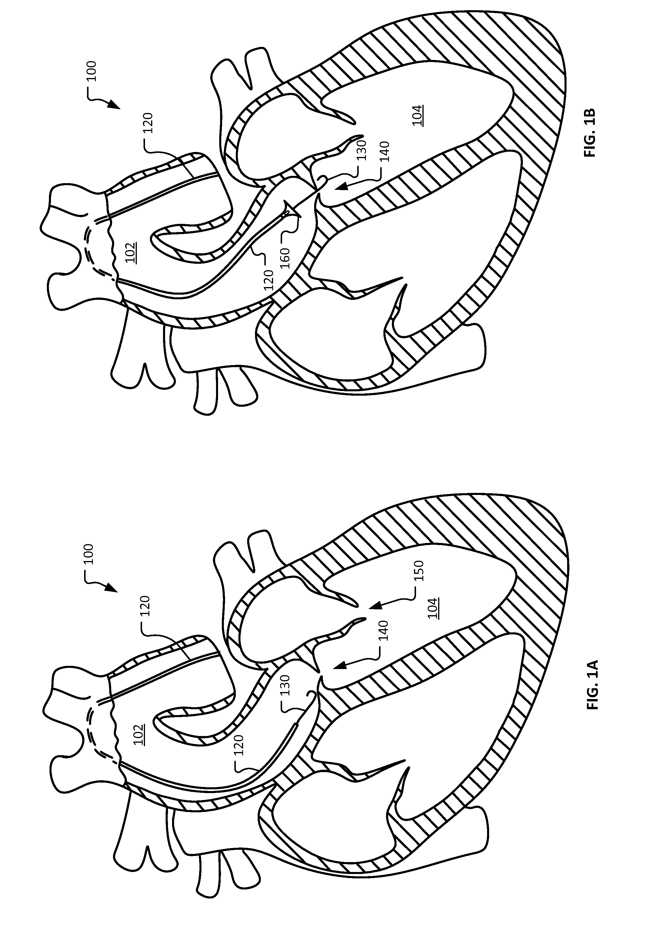
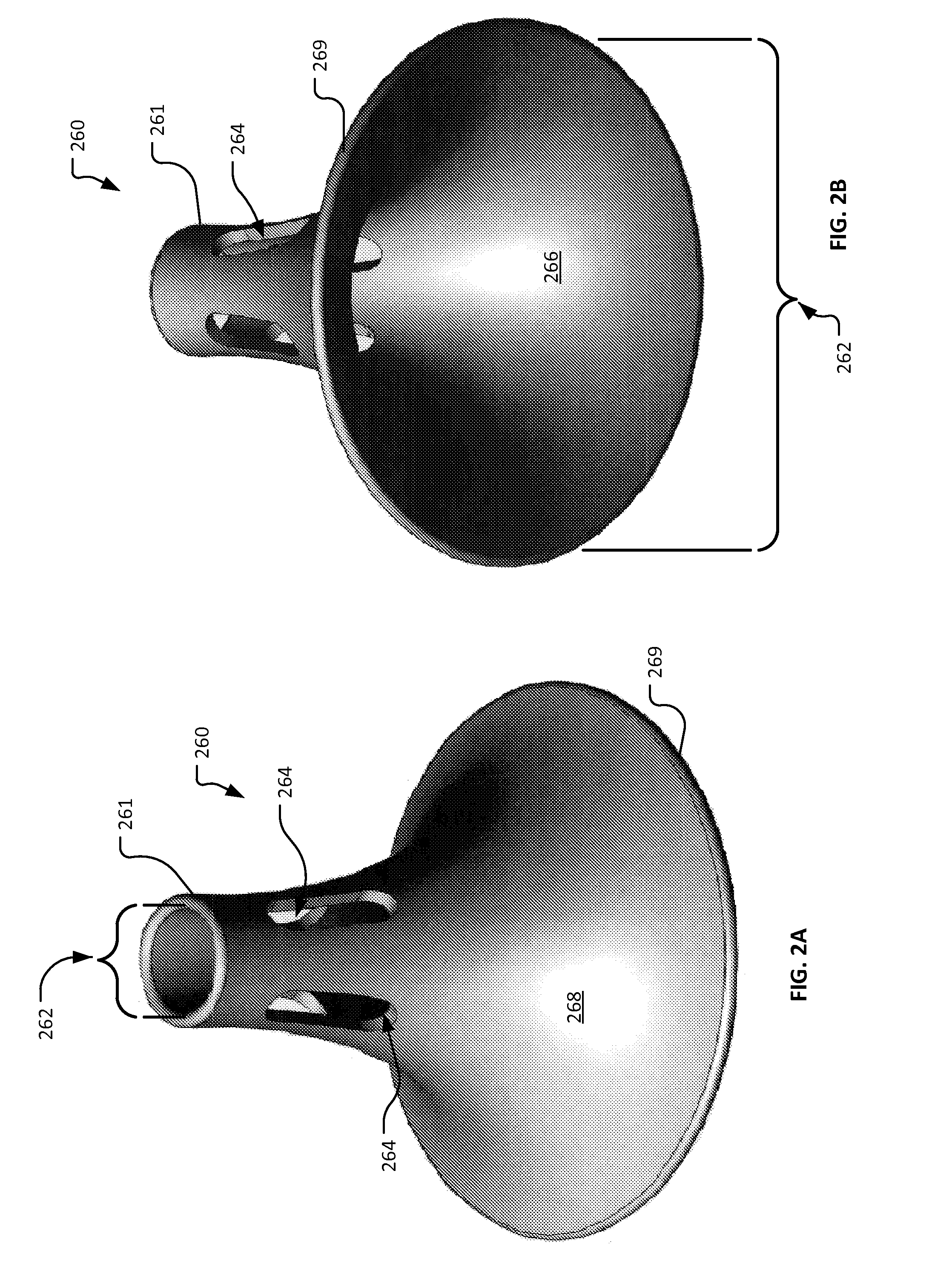
[0029]This document provides devices and methods for the treatment of heart conditions such as valvular stenosis. For example, this document provides devices and methods by which a guide catheter can align itself with a blood flow stream to thereby help direct a guidewire or other elongate device transmitted from the guide catheter through an orifice of a heart valve.

[0030]One of the most challenging steps when performing a TAVR, valvuloplasty, or hemodynamic study on a stenotic valve is to find the valve orifice and pass a guidewire, catheter, or other elongate medical device through the stenotic valve, against the direction of high velocity blood flow. The current practice involves random probing of the stenotic valve with the guide wire until the orifice is penetrated.

[0031]With reference to FIG. 1, a schematic diagram is provided of human heart 100 shown in partial cross-section undergoing a catheterization using a guide catheter 120. Guide catheter 120 is depicted in aortic arc...


PUM


Abstract

This document provides devices and methods for the treatment of heart conditions such as valvular stenosis. For example, this document provides devices and methods by which a guide catheter can align itself with a blood flow stream to thereby help direct a guidewire or other elongate device transmitted from the guide catheter through an orifice of a heart valve.

Description

CROSS-REFERENCE TO RELATED APPLICATIONS[0001]This application claims the benefit of U.S. Provisional Application Ser. No. 61 / 856,910, filed Jul. 22, 2013. The disclosure of the prior application is considered part of (and is incorporated by reference in) the disclosure of this application.BACKGROUND[0002]1. Technical Field[0003]This document relates to devices and methods for the treatment of heart conditions such as valvular stenosis. For example, this document relates to devices and methods by which a guide catheter can align itself with a blood flow stream to thereby help direct a guidewire or other elongate device transmitted from the guide catheter through an orifice of a heart valve, or any other normal or abnormal passage in the body against the direction flow. This device can also be used to localize and repair leaks where a fluid flow jet is present in submerged or fluid-filled chambers.[0004]2. Background Information[0005]Cardiac valvular stenosis is a condition in which t...

Claims


Application Information

Patent Timeline
Patent Type & Authority Applications(United States)
IPC IPC(8): A61F2/24A61M25/01A61M25/09A61M25/04
CPCA61F2/2427A61M25/09A61M25/0108A61M25/04
Inventor SANDHU, GURPREET S.SPOON, DANIEL B.TEFFT, BRANDON J.
Owner MAYO FOUND FOR MEDICAL EDUCATION & RES
Learn More