
Power Battery

a power battery and battery technology, applied in the field of power batteries, can solve the problems of lithium ion batteries, battery heat produced in the working process cannot be released in time, lithium ion batteries bring harm and damage to users, etc., and achieve the effect of less cycles, safer use of power batteries, and long charging tim

Inactive Publication Date: 2016-06-02
YINLONG ENERGY CO LTD
View PDF2 Cites 0 Cited by
  • Summary
  • Abstract
  • Description
  • Claims
  • Application Information

AI Technical Summary

Benefits of technology

This patent is about a new kind of power battery that has improved safety and performance. It has a specific structure, including an external heat abstractor, an internal heat abstractor, and airways for releasing heat. This design helps to keep the battery cool and reduces the risk of exploding. Additionally, the battery can be equipped with a ventilator or air conditioner to control its temperature. The battery also has a thicker outer case to prevent accidents if there are sudden increases in pressure or temperature. Overall, this new battery has better security, can handle more heat, and has a longer lifespan.

Problems solved by technology

The key factor which affects the safety performance of the lithium ion battery is that the heat of the battery produced in the working process can't be released in time.
Instead, the heat is accumulated gradually and becomes out of control to cause an explosion at last, which will bring harm and damages to the users.
Now the lithium ion battery is solid, which is not good for eliminating heat.
These two kinds of batteries have the same defects of low safety performance, less charge / discharge cycles and bad operational performances as follows:
Due to the whole structure defects of the square battery, the square battery stops the internal heat from being released, so that the outer case of the power battery and the inner electrode plates distort, and the spaces between the inner electrode plates of the battery become unequal, which will affect the charging characteristics and discharging characteristics.
What's more, that the internal heat can't be released will result in the instable performance, explosion and short service life of the battery.
Due to the whole structure defects of the circular battery, the circular battery stops the internal heat from being released, so that the spaces between the inner electrode plates of the battery become unequal, which will affect the charging characteristics and discharging characteristics.
What's more, that the internal heat can't be released will result in the instable performance, explosion and short service life of the battery.

Method used


Image

  • Power Battery
  • Power Battery
  • Power Battery

Examples


first embodiment

The First Embodiment

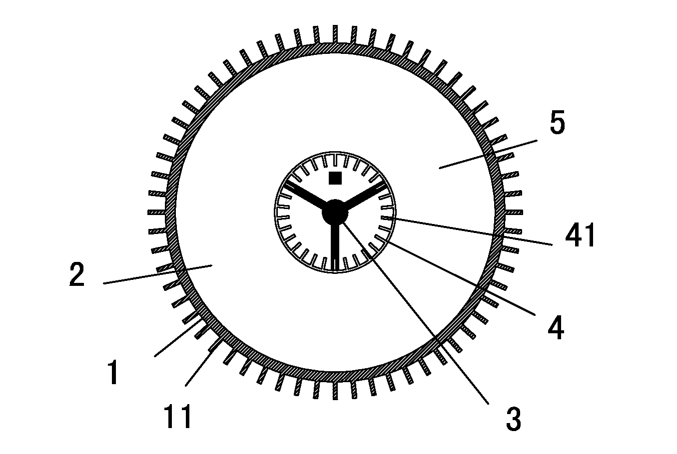
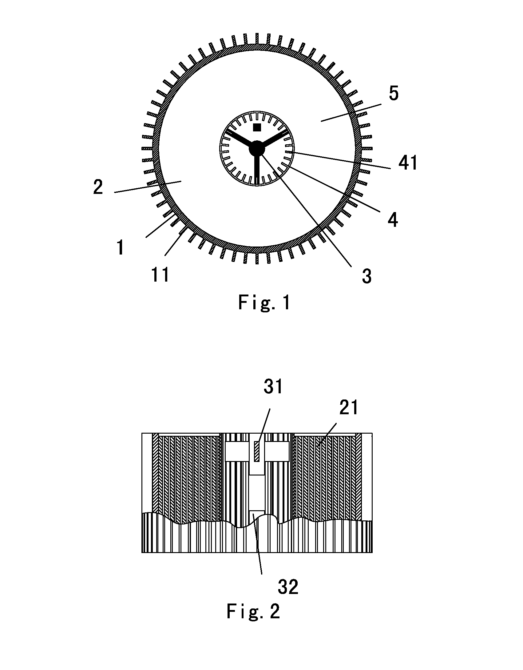
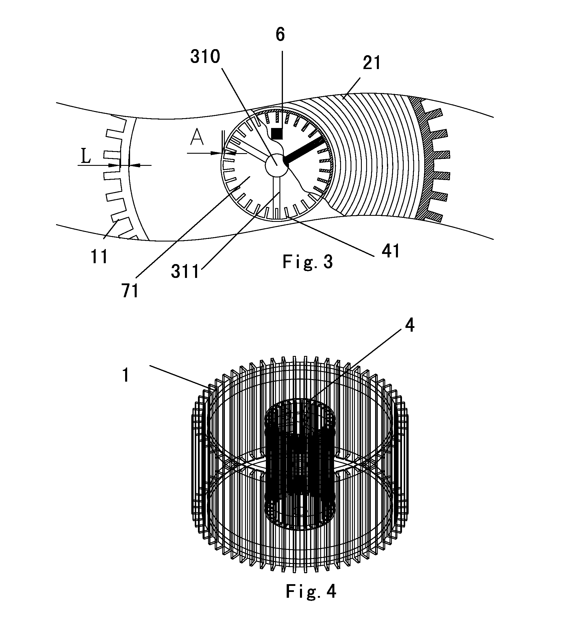
[0042]As shown in FIGS. 1, 2, 3 and 4, according to the power battery of this embodiment, the outer case 1 and the inner case 4 are nested together to form a tubular structure. The external heat abstractor is made up of multiple external radiator fins 11 which extend outwards in directions of diameters of the outer case 1. The multiple external radiator fins 11 are fixed on external surface of the outer case 1 and spaced at a specific distance. The holding cavity 5 has a cylindrical structure with an annular cross section. The electrode plates 21 of the battery body 2 are rolled to form overlapped and sliced cylinders. The internal heat abstractor is made up of multiple internal radiator fins 41 which extend inwards in directions of diameters of the inner case 4. The multiple internal radiator fins 41 are fixed on internal surface of the inner case 4 and spaced at a specific distance. The inner cavity is provided with an airway 71, which has a gear-like cross sec...

second embodiment

The Second Embodiment

[0048]As shown in FIGS. 5, 6, 7 and 8, the power battery disclosed in the second embodiment differs from the first embodiment in that, the inner cavity is provided with an airway 72, which has a quincuncial cross section and may go through the inner cavity; and an irregular surface is formed on the internal surface of the inner case 4, which increases radiating area greatly.

[0049]The wall thickness L of the outer case 1 is ranged from 0.5 mm to 500 mm. The wall thickness B of the inner case 4 is ranged from 0.2 mm to 15 mm.

third embodiment

The Third Embodiment

[0050]As shown in FIGS. 9, 10, 11 and 12, the power battery disclosed in the third embodiment differs from the first embodiment in that, the inner cavity is provided with an airway 73, which has a honeycomb-like cross section and may go through the inner cavity; the airway 73 is composed of multiple small cylindrical honeycomb holes which are not interconnected; and wall thickness of each small honeycomb hole is ranged from 0.5 mm to 1.0 mm.

[0051]The wall thickness L of the outer case 1 is ranged from 0.5 mm to 500 mm. The wall thickness C of the inner case 4 is ranged from 0.2 mm to 15 mm.


PUM


Abstract

A power battery, the power battery includes an inner case (4), an outer case (1), a battery body (2) and electrodes (3), the battery body (2) includes electrode plates, the external surface of the outer case is provided with an external heat abstractor and the internal surface of the inner case is provided with an internal heat abstractor, a cylindrical holding cavity (5) with an annular cross section is formed between the outer case (1) and the inner case (4) and the electrode plates are rolled in the holding cavity (5), the electrodes (3) are arranged in an inner cavity of the inner case (4) and the inner case also has at least an airway going through the inner cavity.

Description

CROSS-REFERENCE TO RELATED APPLICATIONS[0001]This application is a continuation of U.S. application Ser. No. 13 / 376,922 filed Dec. 8, 2011, which is a continuation application of PCT Patent Application No. PCT / CN2009 / 000803, filed on Jul. 17, 2009, entitled “Power Battery”, which claims priority from Chinese Patent Application No.200910040186.2, filed on Jun. 11, 2009, entitled “Power Battery”, both of which are hereby incorporated by reference herein.TECHNICAL FIELD[0002]The present invention relates to techniques of batteries, and more particularly, to a power battery.BACKGROUND OF THE INVENTION[0003]With the development of the world economy, the price of the international oil fluctuates violently in recent years, and the oil resource is anticipated to decrease in the future, so oil has already become a bottle neck of the development of the world economy, and making use of new energy sources has become a new trend in the development of economy. With the growing shortage of the glo...

Claims


Application Information

Patent Timeline
Patent Type & Authority Applications(United States)
IPC IPC(8): H01M10/6551H01M10/613H01M10/643H01M2/02H01M50/102H01M50/107
CPCH01M10/6551H01M2/024H01M10/643H01M10/613H01M2/022H01M10/6562H01M10/0431Y02E60/10H01M50/107Y02P70/50H01M10/654H01M2220/20H01M10/6561
Inventor WEI, YINCANG
Owner YINLONG ENERGY CO LTD
Learn More