
Unmanned Aerial Vehicle With Lighting and Cooling Therefor

a technology of unmanned aerial vehicles and cooling devices, which is applied in the direction of transportation and packaging, semiconductor devices for light sources, lighting and heating apparatus, etc., can solve the problems of not being readily visible to observers on the ground, unable to accommodate the heat generated by high-power lights, and significantly limited light provided by the foregoing and other current lighted uavs

Active Publication Date: 2016-06-02
WET ENTERPRISES
View PDF11 Cites 48 Cited by
  • Summary
  • Abstract
  • Description
  • Claims
  • Application Information

AI Technical Summary

Benefits of technology

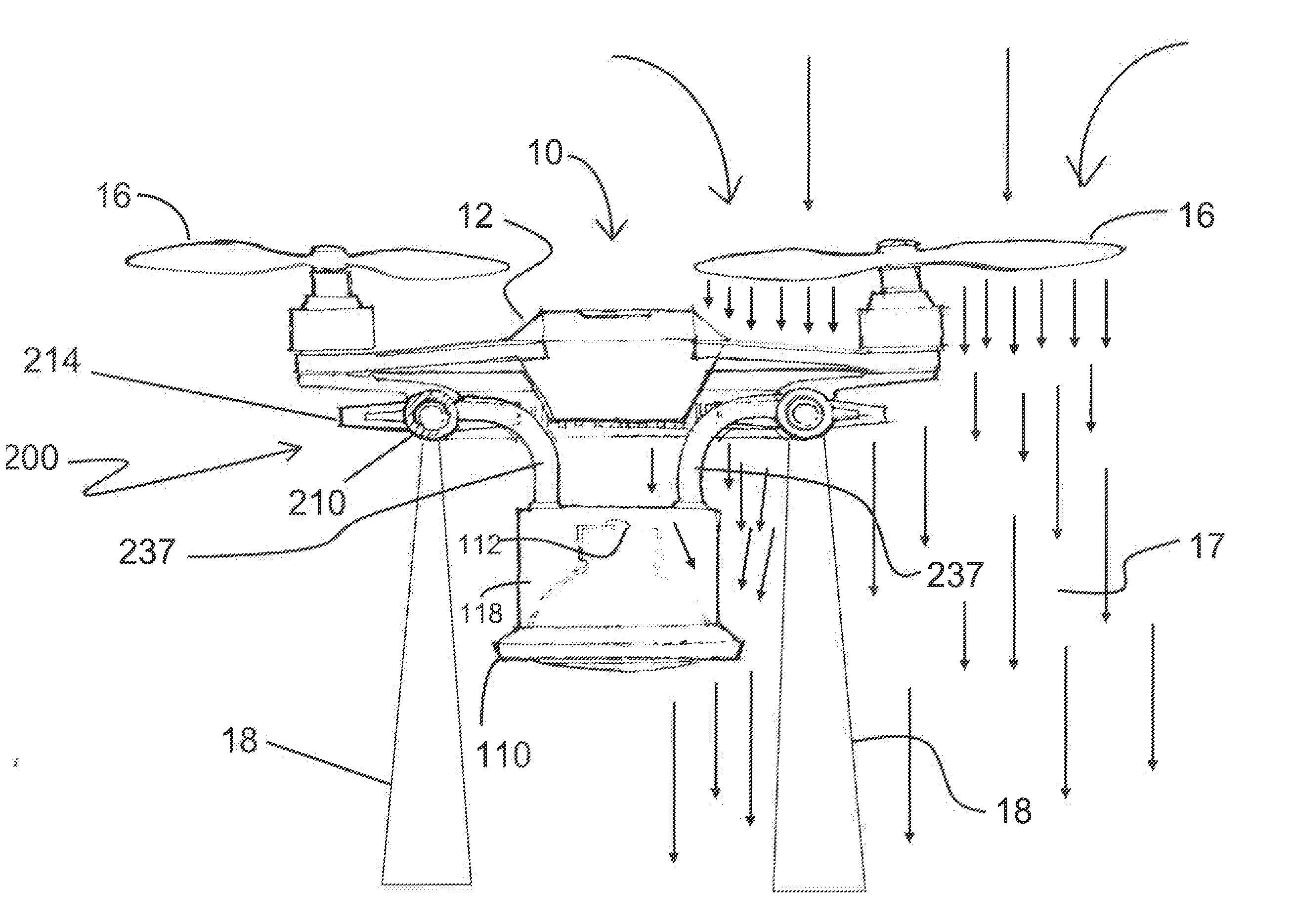
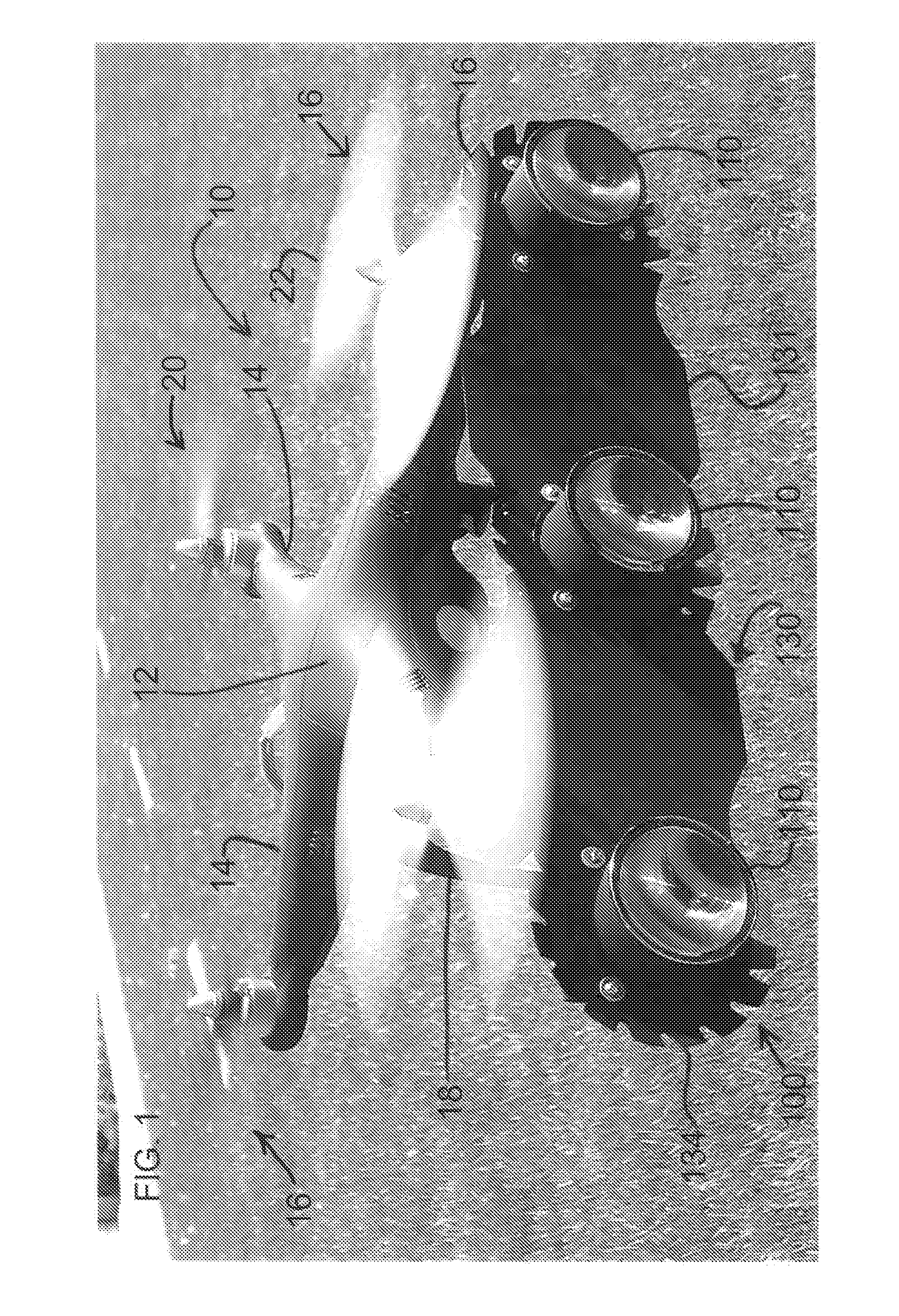
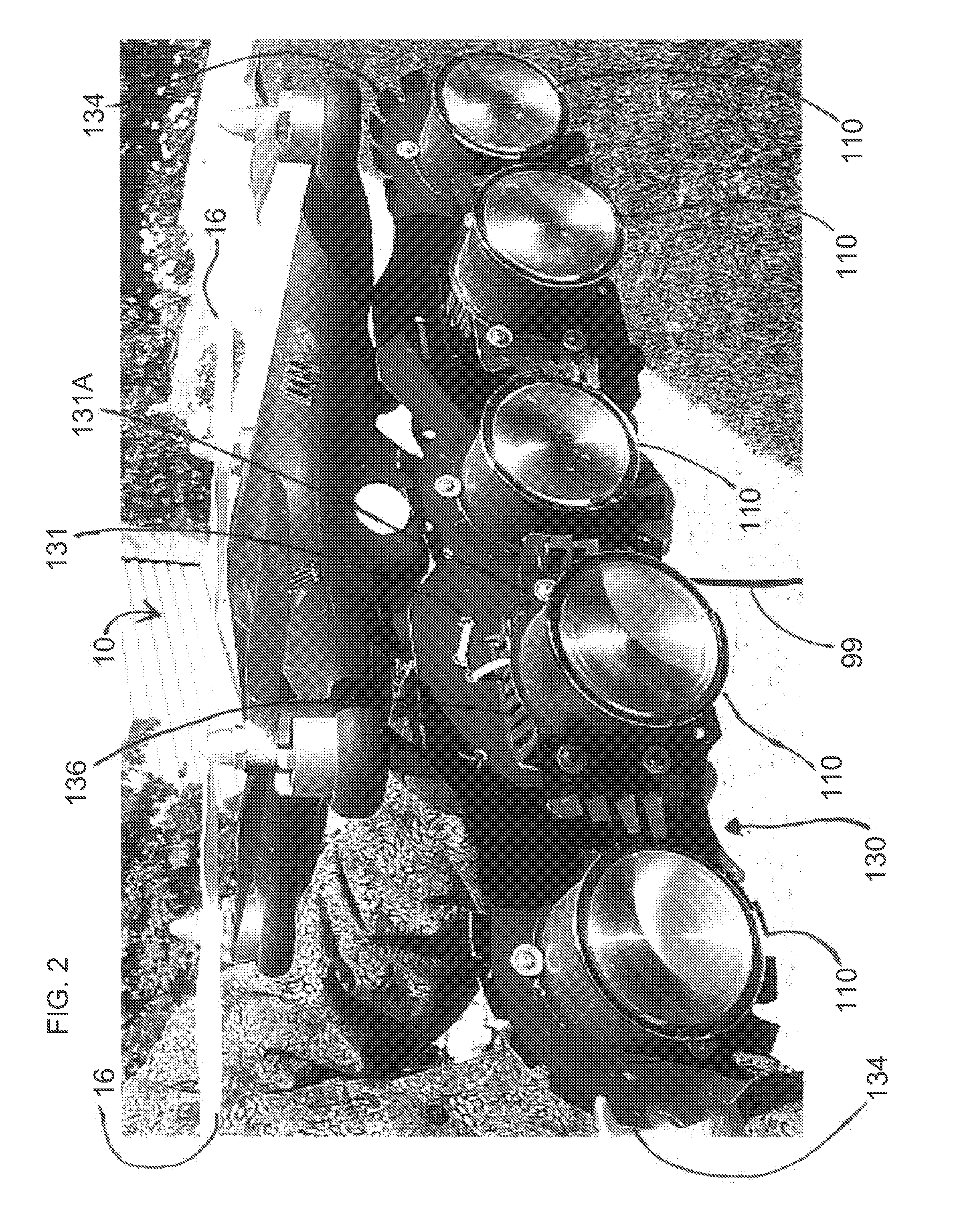
The invention is about a small flying drone that can carry a lighting system and a battery or power source. The drone can also have a radiator or heat exchanger to cool the lights using its airflow. The drone can also be used in connection with a water and lighting display, where the water can cool the drone's lights and the UAV can tow the vessel in the water. Additionally, the drone can carry a laser for creating displays and projections that can be seen in broad daylight, but with safety measures to avoid projecting the laser into viewers' eyes.

Problems solved by technology

However, the amount of light provided by the foregoing and other current lighted UAVs is significantly limited.
For example, current lighted UAVs are generally fitted with lights that do not provide significant lumens.
This is a significant problem where, for example, the UAV is intended to fly high above the ground or otherwise viewed from a great distance.
In this situation, because the light fitted to the UAV does not provide significant lumens, it may not be readily visible to observers on the ground.
A reason why current lighted UAVs are fitted with low power lighting is because they cannot accommodate the heat generated by high-power lights.
For example, LED lights that provide significant lumens also generate significant heat, and none of the above-referenced lighted UAVs address heat issues associated with such powerful LEDs.
Furthermore, simply fitting high-lumen lights to existing UAVs without cooling mechanisms presents other significant heating issues.
For example, many high-lumen LED lights would overheat in a very short time, thereby preventing any type of sustained display time.
In reality, such high-lumen LEDs could create a fire in a short amount of time if not cooled.
In this case, even one minute flight display times are not possible, and such heat could disable the aircraft and cause a safety hazard to viewers.
In any event, requiring a UAV to land after a very short flight time to avoid overheating the light or heat damage to the UAV severely limits the manners in which the UAV may be used.
Beyond cooling issues existing with high-lumen lights, the UAV may include other components such as electrical circuits, motors, and the like that generate heat and that may fail without cooling if the UAV operates those devices for extended periods.
The above-referenced lighted UAVs do not address this issue.

Method used


Image

  • Unmanned Aerial Vehicle With Lighting and Cooling Therefor
  • Unmanned Aerial Vehicle With Lighting and Cooling Therefor
  • Unmanned Aerial Vehicle With Lighting and Cooling Therefor

Examples


Embodiment Construction

[0043]The following detailed description is not intended to limit the current invention, in that alternate embodiments will be apparent to those skilled in the art. For example, some of the lighting and cooling systems of the current invention may assume different configurations and may be fitted to different types of UAVs. Furthermore, one or more different types of lighting and / or cooling mechanisms may be used. In the figures, the same or similar reference numerals may refer to the same or similar elements throughout the different views, as well as within the description below.

[0044]The current invention addresses the significant and potentially debilitating heat that may be generated by today's high-lumen lights, such as LEDs and lasers. For example, in connection with LED testing in connection with the current invention, normal operation of a free-standing LED was observed up to a temperature of 85 degrees Celsius, which can provide 70% of the regular operational output of the ...


PUM


Abstract

An unmanned aerial vehicle (UAV) that includes a light and a cooling system is described. The light fitted to the UAV may be bright since heat it generates will be cooled by thermal conduction, convection and / or heat absorption. The light may be cooled by the airflow generated by the propellers. The cooling system of the lighted UAV may include radiator that may conduct heat to the environment and / or include an internal liquid cooling system. The cooling system may include dedicated fans to cool the lights.

Description

CROSS REFERENCE TO RELATED APPLICATION[0001]The application claims the benefit of U.S. Provisional Application No. 62 / 067,978, filed Oct. 23, 2014, the contents of which are incorporated herein by reference.FIELD OF THE INVENTION[0002]The field of the invention generally relates to unmanned aerial vehicles (UAVs), including UAVs that are fitted with one or more lights and cooling mechanisms therefor.BACKGROUND OF THE INVENTION[0003]In recent years, UAVs have been developed and put into use in different applications. Besides UAVs such as large drones used in military applications, smaller consumer-level UAVs have recently become more popular in civilian applications due to their ease of use. For example, smaller self-stabilizing UAVs are now commonly used by aviation enthusiasts with little or no flight training, similar to how small-scale airplanes and helicopters have been used by skilled hobbyists for some time.[0004]More recently, UAVs have been used as display items, to carry ob...

Claims


Application Information

Patent Timeline
Patent Type & Authority Applications(United States)
IPC IPC(8): B64D47/06B64C27/08B64C39/02F21W107/30
CPCB64D47/06B64C39/024B64C2201/108B64C2201/027B64C27/08B64D47/04F21V29/677F21V29/83F21Y2115/10F21W2107/30B64U30/20
Inventor MOLNAR, DEZSOCANAVAN, JOHN
Owner WET ENTERPRISES
Learn More