
Article comprising a microneedle

Active Publication Date: 2016-06-02
KINDEVA DRUG DELIVERY LP
View PDF5 Cites 5 Cited by
  • Summary
  • Abstract
  • Description
  • Claims
  • Application Information

AI Technical Summary

Benefits of technology

This patent is about an article made up of small needles that can be used to penetrate the skin. When the needles are pressed against the skin, they can cause discomfort and uneven penetration depth. The patent proposes a solution by including certain features in the design of the article. These features allow for consistent and reliable insertion of the needles to a desired depth in the skin, while minimizing discomfort. The patent also proposes simpler and more robust manufacturing processes for the article. Overall, the patent provides technical means to improve the performance and comfort of articles made up of small needles for skin penetration.

Problems solved by technology

It has now been found that an interaction between an article comprising a plurality of hollow microneedles and a skin surface against which the article is urged can result in undesirable effects on the penetration of at least one microneedle of the plurality into the skin.

Method used


Image

  • Article comprising a microneedle
  • Article comprising a microneedle
  • Article comprising a microneedle

Examples


example 1

Fabrication of Microneedle Articles

[0165]The microneedle articles were prepared from polymeric material using standard injection molding procedures. The molded microneedle articles were prepared using a mold assembly prepared from three mold sections with each section machined from steel. The first mold section contained projections that defined the beveled shape of the needle tip in the molded array. Each projection in the first mold section had a further cylindrical extension that defined features of the tip segment of the microneedles tip, including the opening on a bevel proximate the tip of the microneedle and a portion of the hollow channel extending through the body of each microneedle. The second mold section served as a template to define the pattern of the microneedles in the molded article, the external shape and size of the microneedles in the molded article, and the first side of the article (including the central cavity portion, platform portion, and peripheral portion...

example 2

Injection Apparatus used to Test the Microneedle Articles

[0167]Fully assembled microneedle article injection apparatuses similar to apparatuses described in U.S. Patent Application Publication No. US2012 / 0123387 (FIGS. 1-13) and U.S. Provisional Patent Application No. 61 / 740,941 (FIGS. 2, 14 and 15) were used. The drug cartridge in each apparatus contained al mL solution of 0.005% methylene blue in five percent aqueous dextrose. The injection apparatus from Example 1 of U.S. Provisional Patent Application No. 61 / 740,941 was used with the following exceptions. First, the section of the apparatus joined to the adhesive assembly was not milled to remove material. Second, the construction of the adhesive assembly was different. Instead of using the four layer adhesive of U.S. Provisional Patent Application No. 61 / 740,941, the adhesive assembly used was a laminate composed of only two layers. The first layer was a 0.10 mm thick sheet of 3M 1510 double sided tape (available from the 3M Co...

example 3

Injection Apparatus

[0169]The same microneedle injection apparatus as described in Example 2 was used with the exception that the wire diameter of the U-shaped leaf-like insertion spring (i.e. first stored energy device as described in U.S. Patent Application Publication No. US2012 / 0123387 (FIGS. 1-13) and U.S. Provisional Patent Application No. 61 / 740,941 (FIGS. 2, 14 and 15)) was 1.50 mm instead of 1.59 mm.


PUM


Abstract

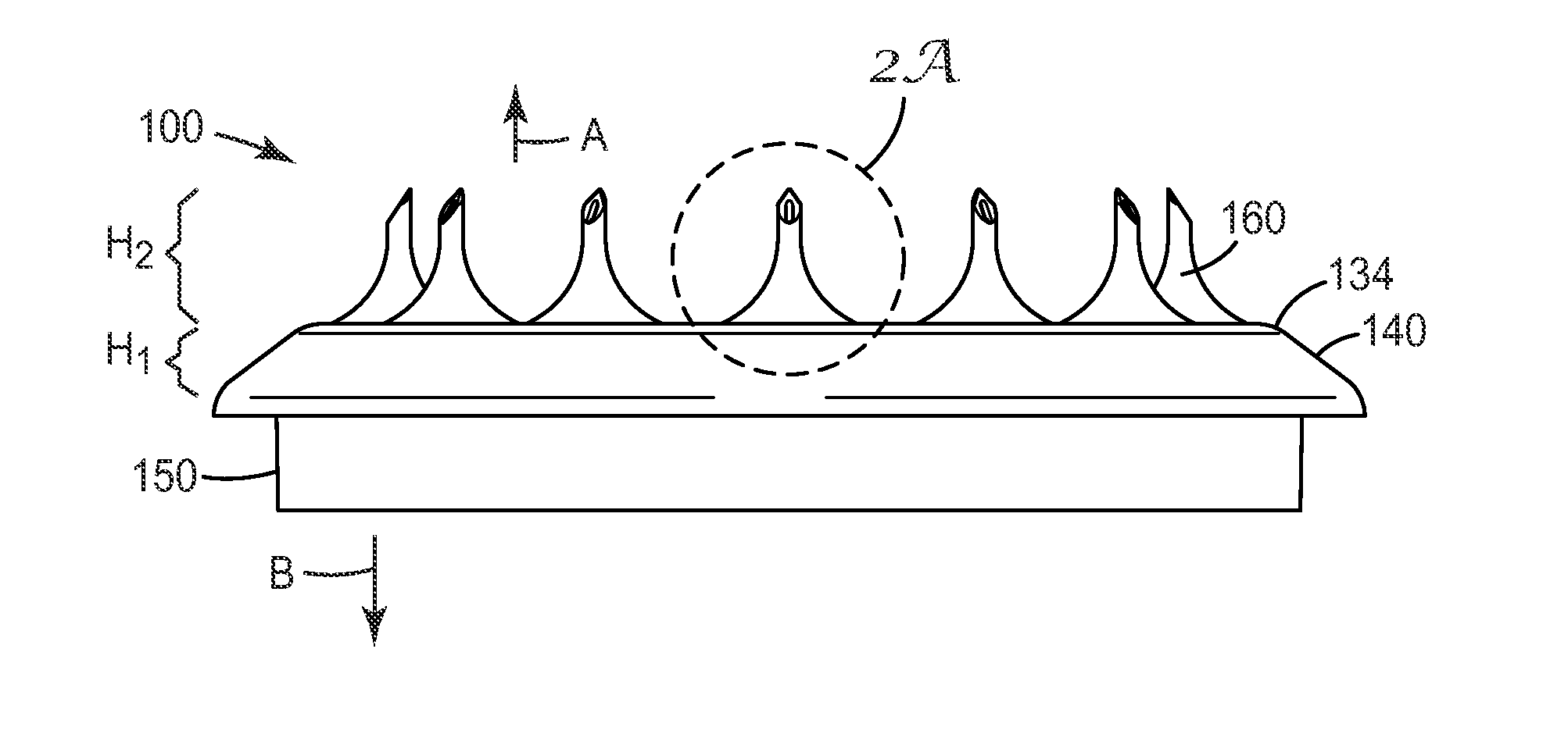
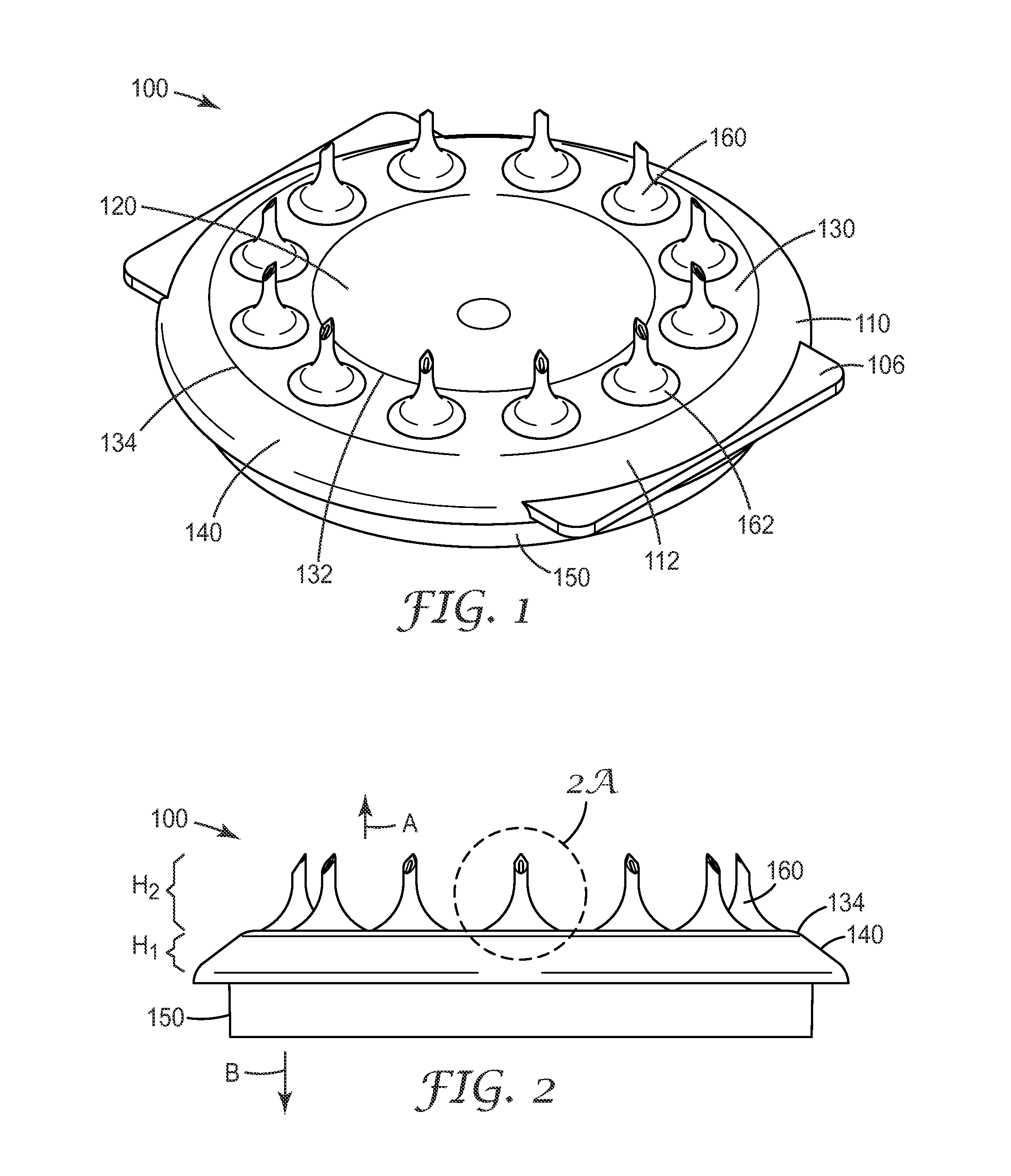
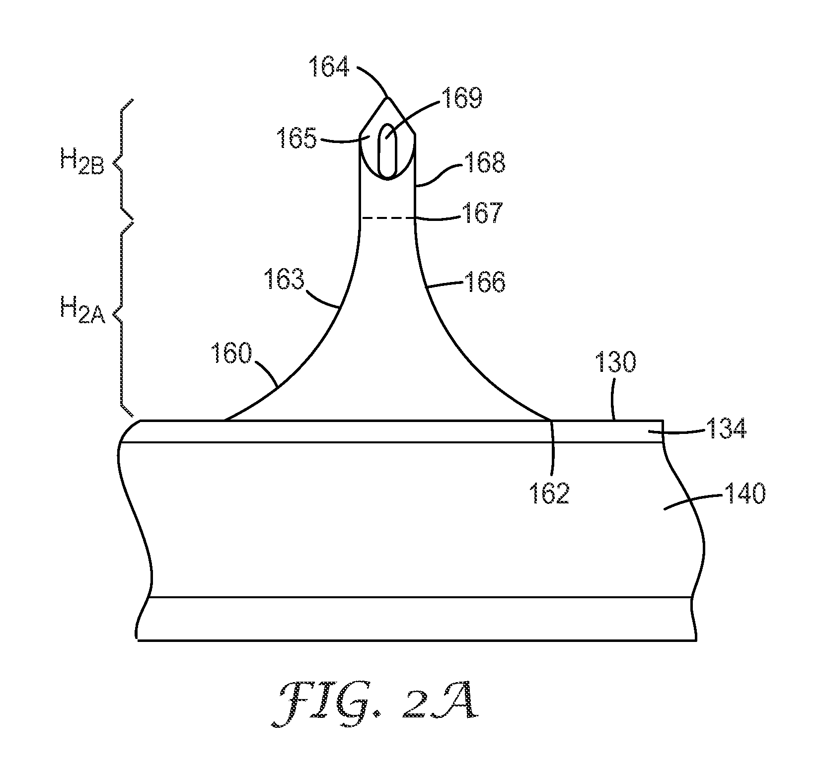
An article 100 comprising at least one microneedle 160 is provided. The article comprises a first side 112 and a second side 114 opposite the first side. The first side comprises a central cavity portion 120 and a platform portion 130, with at least one microneedle extending therefrom, wherein the platform portion is not coplanar with the central cavity portion. The platform portion substantially surrounds the central cavity portion. The at least one microneedle 160 comprises a body comprising an outer surface 163; a base segment 166 having a base and a first shape; a tip segment 168 having a tip 164 and a second shape, wherein the second shape is distinct from the first shape; a transition plane 167 that delineates the base segment and the tip segment; and a central axis.

Description

CROSS REFERENCE TO RELATED APPLICATIONS[0001]This application claims priority to U.S. Provisional Patent Application No. 61 / 846,909, filed Jul. 16, 2013, the disclosure of which is incorporated by reference in its entirety herein.BACKGROUND[0002]Transdermal and topical drug delivery can be used for therapeutic treatment, but the number of molecules that can be effectively delivered using these routes can be limited by the barrier properties of skin. The main barrier to transport of molecules through the skin is the stratum corneum (the outermost layer of the skin).[0003]A number of different skin treatment methods have been proposed in order to increase the permeability or porosity of the outermost skin layers, such as the stratum corneum, thus enhancing drug delivery through or into those layers. The stratum corneum is a complex structure of compact keratinized cell remnants separated by lipid domains. The stratum corneum is formed of keratinocytes, which comprise the majority of e...

Claims


Application Information

Patent Timeline
IPC IPC(8): A61M37/00
CPCA61M2037/0023A61M37/0015A61M2037/003A61M2037/0061
Inventor BERRY, DENNIS G.MARTINSON, PAUL A.NG, CHIN-YEESIMMERS, RYAN PATRICK
Owner KINDEVA DRUG DELIVERY LP
Learn More