
Liquid-crystal display device

a liquid crystal display and display device technology, applied in non-linear optics, instruments, optics, etc., can solve the problems of high manufacturing cost, and achieve the effect of improving front surface luminance and color reproduction region

Active Publication Date: 2016-05-26
FUJIFILM CORP
View PDF4 Cites 14 Cited by
  • Summary
  • Abstract
  • Description
  • Claims
  • Application Information

AI Technical Summary

Benefits of technology

This patent is about a new liquid-crystal display device that improves brightness and color reproduction. It does this by using a polarization separating member, a light conversion member sheet, and a blue light source. This arrangement increases the amount of light that is saved by improving the device's light utilization ratio. It also enhances the display's color reproduction region, making it better than using a broadband white light source. Overall, this patent provides a cost-effective solution for improving the performance of liquid-crystal display devices.

Problems solved by technology

In JP3448626B and JP1989-133003A (JP-H1-133003A) in which the light utilization ratio is improved, since a broadband light recycling function with respect to white light is imparted, the design becomes complicated due to a multilayer constitution and the wavelength dispersibility of the members, and thus there is a problem of high manufacturing costs.

Method used


Image

  • Liquid-crystal display device
  • Liquid-crystal display device
  • Liquid-crystal display device

Examples


example 1

Manufacturing of Polarization Separating Member

[0217](Formation of First λ / 4 Plate)

[0218]With reference to JP2012-108471A, a first λ / 4 plate (B narrowband λ / 4 plate) was formed on a commercially available cellulose acylate-based film “TD60” (manufactured by Fujifilm Corporation) using a discotic liquid crystal compound.

[0219]The obtained first λ / 4 plate had a Re (450) of 112 nm, a Re (550) of 93 nm, and a film thickness of 2.2 μm.

[0220](Formation of Light Reflection Layer Formed by Fixing Cholesteric Liquid Crystalline Phase)

[0221]With reference to pp. 60 to 63 of Fujifilm Research & Development No. 50 (2005), a light reflection layer formed by fixing a cholesteric liquid crystalline phase was formed by means of coating on a support by changing the added amount of a chiral agent used.

[0222]The obtained light reflection layer formed by fixing a cholesteric liquid crystalline phase had a reflection central wavelength of the peak of the maximum reflection ratio of 445 nm, a half width ...

example 2

[0243]With reference to JP2009-199001A, a prism sheet was manufactured.

[0244]A liquid-crystal display device of Example 2 was manufactured in the same manner as in Example 1 except for the fact that, in Example 1, the prism sheet manufactured above was disposed between the polarization separating film 1 and the quantum rod-aligned sheet 1.

reference example 1

[0245]A commercially available liquid-crystal display device (manufactured by Panasonic Corporation, trade name: TH-L42D2) was disassembled, the polarizing plate 1 manufactured in Manufacturing Example 1 was used as the backlight-side polarizing plate, and a dielectric multilayer film (RGB) (trade name: DBEF, manufactured by 3M Company, a film thickness of 25 μm) was separated without providing an adhesive layer and was disposed between the backlight-side polarizing plate and the backlight unit, thereby manufacturing a liquid-crystal display device of Reference Example 1.

[0246]The dielectric multilayer film (RGB) had an almost constant flat peak of the reflection ratio with respect to wavelengths in the blue to green to red region of 450 nm to 550 nm to 630 nm.

[0247]Meanwhile, a white backlight light source (hereinafter, also referred to as W light source) in the liquid-crystal display device had a light emission peak wavelength of blue light at 450 nm.


PUM

PropertyMeasurementUnit
wavelength rangeaaaaaaaaaa

Abstract

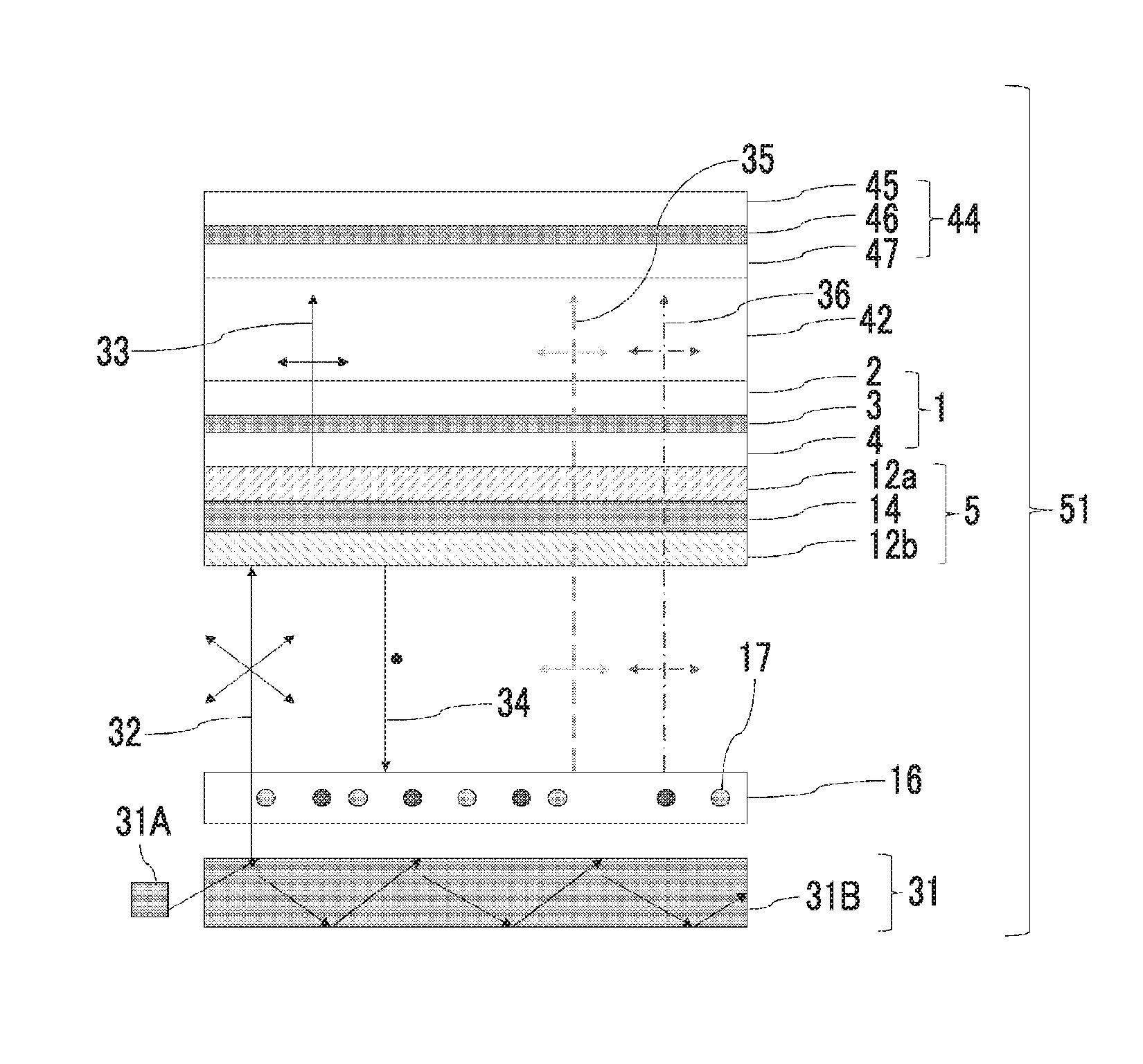
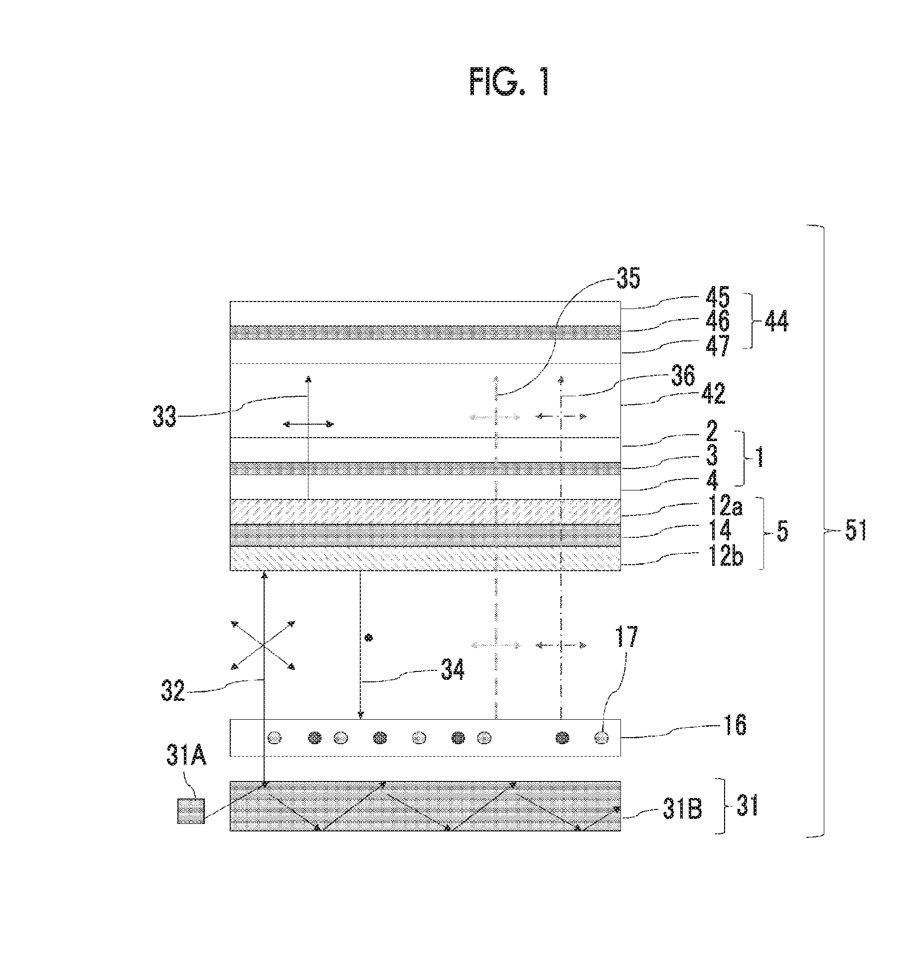
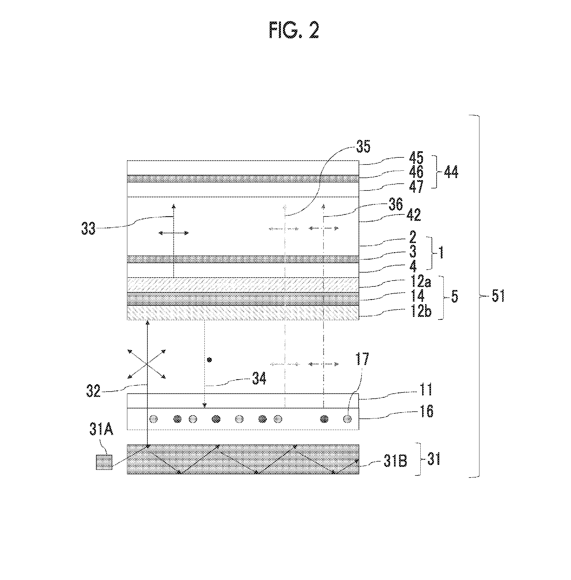
A liquid-crystal display device having a backlight unit emitting unpolarized blue light, a light conversion member, a polarization separating member, a backlight-side polarizer, a liquid crystal cell, and a display-side polarizing plate wherein the polarization separating member separates the unpolarized blue light into blue transmitted light and blue reflected light which are linearly polarized in vibration directions that are orthogonal to each other, and transmits some of light in a wavelength range each of 500 nm to 600 nm and 600 nm to 650 nm, the light conversion member includes a fluorescent material that, due to blue light entering the light conversion member, emits green light which is linearly-polarized light and red light which is linearly-polarized light; and a transmission axis of the backlight-side polarizer is parallel to vibration directions of the green and red light, is improved in terms of front surface luminance and color reproduction region.

Description

CROSS-REFERENCE TO RELATED APPLICATIONS[0001]This application is a Continuation of PCT International Application No. PCT / JP2014 / 069310, filed on Jul. 22, 2014, which claims priority under 35 U.S.C. Section 119(a) to Japanese Patent Application No. 2013-152055 filed on Jul. 22, 2013 and Japanese Patent Application No. 2014-146852 filed on Jul. 17, 2014. Each of the above applications is hereby expressly incorporated by reference, in its entirety, into the present application.BACKGROUND OF THE INVENTION[0002]1. Field of the Invention[0003]The present invention relates to a liquid-crystal display device.[0004]2. Description of the Related Art[0005]A liquid-crystal display device (hereinafter, also referred to as LCD) has been used in a broadening range of fields every year as an image display device which has low power consumption and saves spaces. A liquid-crystal display device has a constitution in which a backlight (hereinafter, also referred to as BL), a backlight-side polarizing ...

Claims


Application Information

Patent Timeline
Patent Type & Authority Applications(United States)
IPC IPC(8): G02F1/1335G02F1/13363
CPCG02F1/13362G02F1/133621G02F1/133528G02F2001/133638G02F1/133536G02F1/133617G02F2001/133614G02F1/13363G02F1/133614G02F1/133638
Inventor SANETO, RYUJIOHMURO, KATSUFUMI
Owner FUJIFILM CORP
Learn More