
Method of flying an aircraft

a technology of aircraft and wings, applied in the field of aircraft flying, can solve the problems of difficult high-speed flying for conventional aircraft, easy impact on conventional aircraft, and inability to fly at high speed, so as to reduce the duration of flight, reduce the effect of fuel consumption during descent, and allow the reduction of fuel consumption

Inactive Publication Date: 2016-05-26
KIKUCHI NAOMI
View PDF4 Cites 1 Cited by
  • Summary
  • Abstract
  • Description
  • Claims
  • Application Information

AI Technical Summary

Benefits of technology

The present invention allows for a reduction in flight duration and fuel consumption by flying at high altitudes. Additionally, it provides larger lifting powers and sufficient thrusts to travel through the atmosphere and high altitudes with reduced atmospheric pressure.

Problems solved by technology

Hence, such conventional aircrafts have no choice but to fly in relatively low altitude.
Moreover, conventional aircrafts are easily affected by large air resistances in a direction opposite to the moving direction when flying at low altitude since atmospheric pressure is high in such low altitudes.
For this reason, aircrafts get decelerated due to such air resistances, thereby making it difficult for them to fly at high speeds.
Further, when traveling long distances, conventional aircrafts have a problem of taking a fair amount of time traveling therethrough.
Furthermore, due to the large air resistances, conventional aircrafts have a problem of spending too much engine fuels for generating a thrust.

Method used


Image

  • Method of flying an aircraft
  • Method of flying an aircraft
  • Method of flying an aircraft

Examples


Embodiment Construction

[0022]Preferred embodiments of the present invention are described with reference to the accompanying drawings. However, the embodiments described hereunder shall not limit the contents of the present invention that are found in the scope of claims. Further, not all elements described hereunder are necessarily the essential elements of the present invention.

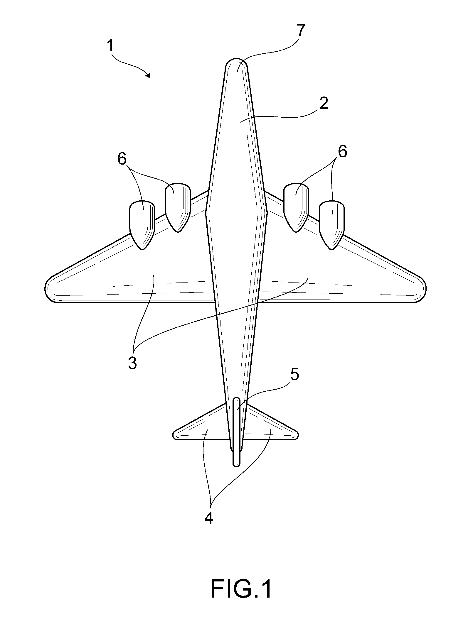
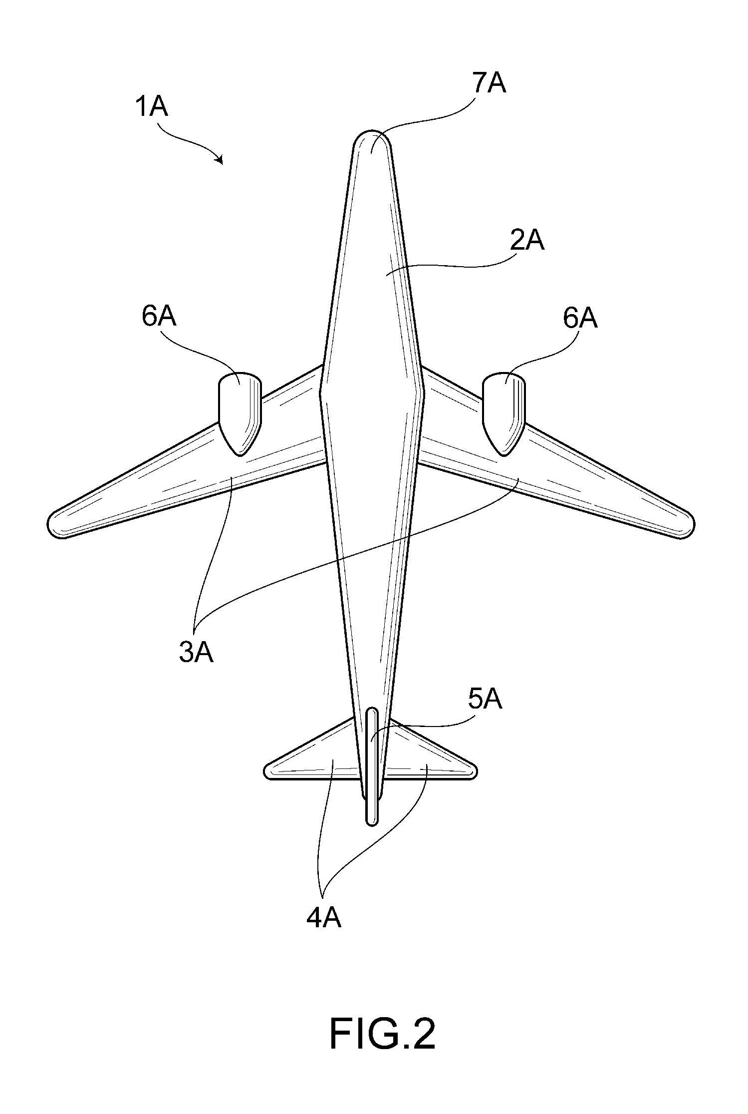
[0023]An embodiment of the present invention will be described hereunder with reference to FIGS. 1 to 3.

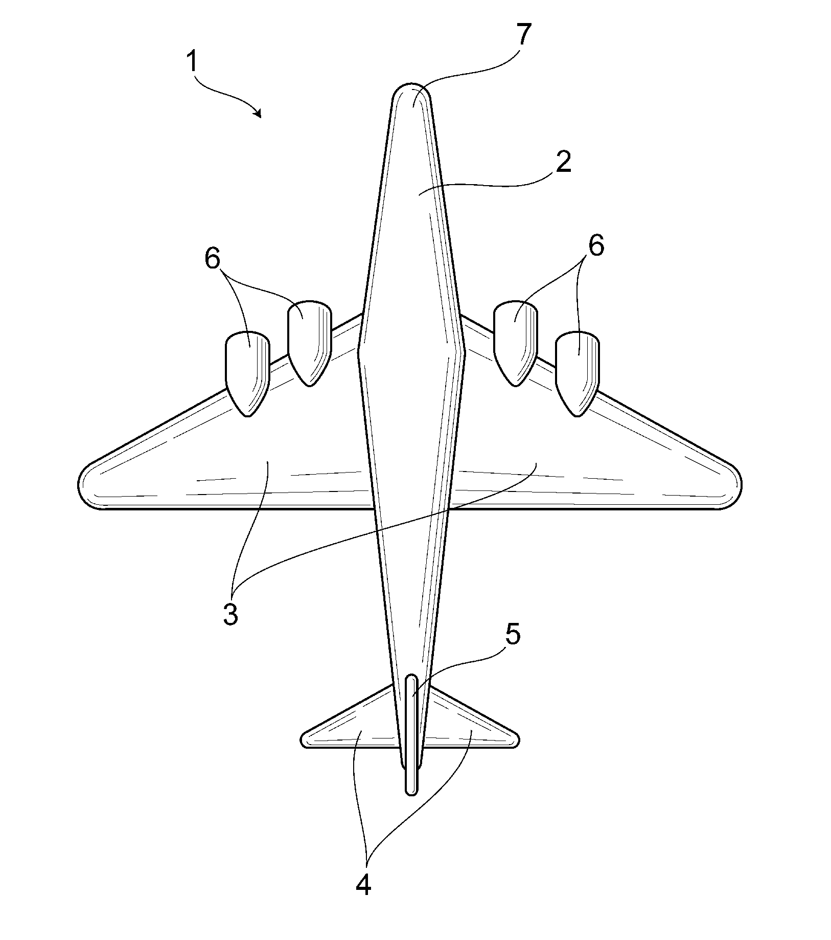
[0024]FIG. 1 shows an aircraft 1 according to one embodiment of the present invention. The aircraft 1 comprises a fuselage 2, primary wings 3 attached to the lateral sides of the fuselage 2 and provided in about a middle portion in a front-rear direction of the fuselage 2, tail-planes 4 attached to the lateral sides of the fuselage 2 and provided in the rear of the body 2, a vertical tail 5 attached to the upper side of the fuselage 2 and provided in the vicinity of the rear end of the fuselage 2, and engine(s) 6 serving as dri...


PUM


Abstract

Provided is a fuel-efficient method of flying an aircraft for flying an aircraft. The present invention relates to a method of flying an aircraft 1 having a fuselage 2, primary wings 3, and high-power engines 6 serving as driving units for generating a thrust. The method of flying an aircraft comprising: determining a combination of said primary wings 3 and high-power engines 6 so that a total wing area of said primary wings 2 is proportionally correlated to an power output of said high-power engines 6, generating a comparatively large lifting power using said primary wings 3 having large wing areas, elevating said aircraft 1 to a high altitude, and flying said aircraft 1 at high speeds and altitudes using said high-power engine 6.

Description

BACKGROUND OF THE INVENTION[0001]1. Field of the Invention[0002]The present invention relates to a method of flying an aircraft enabling high-speed and fuel-efficient flying.[0003]2. Background Art[0004]Conventionally, there are known aircrafts as disclosed, for example, in FIG. 1 of Japanese Unexamined Patent Application Publication No. H05-286498. Such aircrafts include a single engine provided for each one of the left-and-right primary wings. For that reason, power outputs of the engines are not large enough, thereby being not capable of producing large thrusting powers, thus making it difficult for the aircrafts to fly at high speeds.[0005]Further, a total wing area such primary wings are not sufficiently large and thus lifting powers produced by primary wings are not large enough, thereby making it difficult for the aircrafts to be elevated to a high altitude.SUMMARY OF THE INVENTION[0006]Hence, such conventional aircrafts have no choice but to fly in relatively low altitude. M...

Claims


Application Information

Patent Timeline
IPC IPC(8): B64D27/18B64C3/10B64D27/02
CPCB64D27/18B64C3/10B64D27/023B64D27/12
Inventor KIKUCHI, NAOMI
Owner KIKUCHI NAOMI
Learn More