
Cushion pad

a technology of cushion and cushion, which is applied in the field of cushion pads, can solve problems such as inability to sit upright, achieve the effects of improving texture and fit feeling, reducing the sinking of the buttocks, and small hardness

Active Publication Date: 2016-05-26
TOKYO QUALITY ONE CORP
View PDF12 Cites 6 Cited by
  • Summary
  • Abstract
  • Description
  • Claims
  • Application Information

AI Technical Summary

Benefits of technology

The cushion pad described in this patent has a unique design that supports the buttocks and thighs of a seated person. The pad has different hardness levels in different areas to provide better support and comfort. The under-buttock portion has a softer hardness to improve the texture and fit feeling, while the thigh supporting portion has a softer hardness to reduce the feeling of oppression in the thighs. The pad can be made using a single foam material, which eliminates the need for multiple layers with different hardness levels and reduces manufacturing costs. Overall, the cushion pad provides better support and comfort for the seated person.

Problems solved by technology

On the other hand, when the hardness of the under-buttock portion is set corresponding to the hardness of the thigh supporting portion, the sinking of the buttocks becomes large so as to cause an unstable seating posture.

Method used


Image

  • Cushion pad
  • Cushion pad
  • Cushion pad

Examples


first embodiment

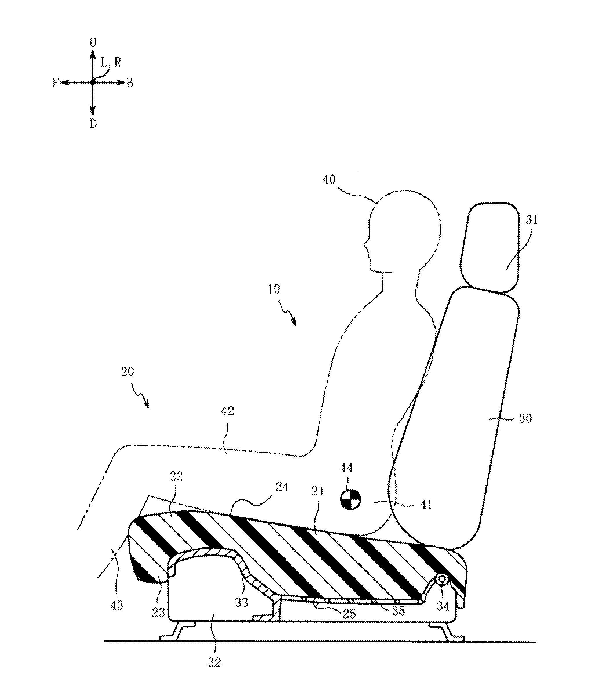
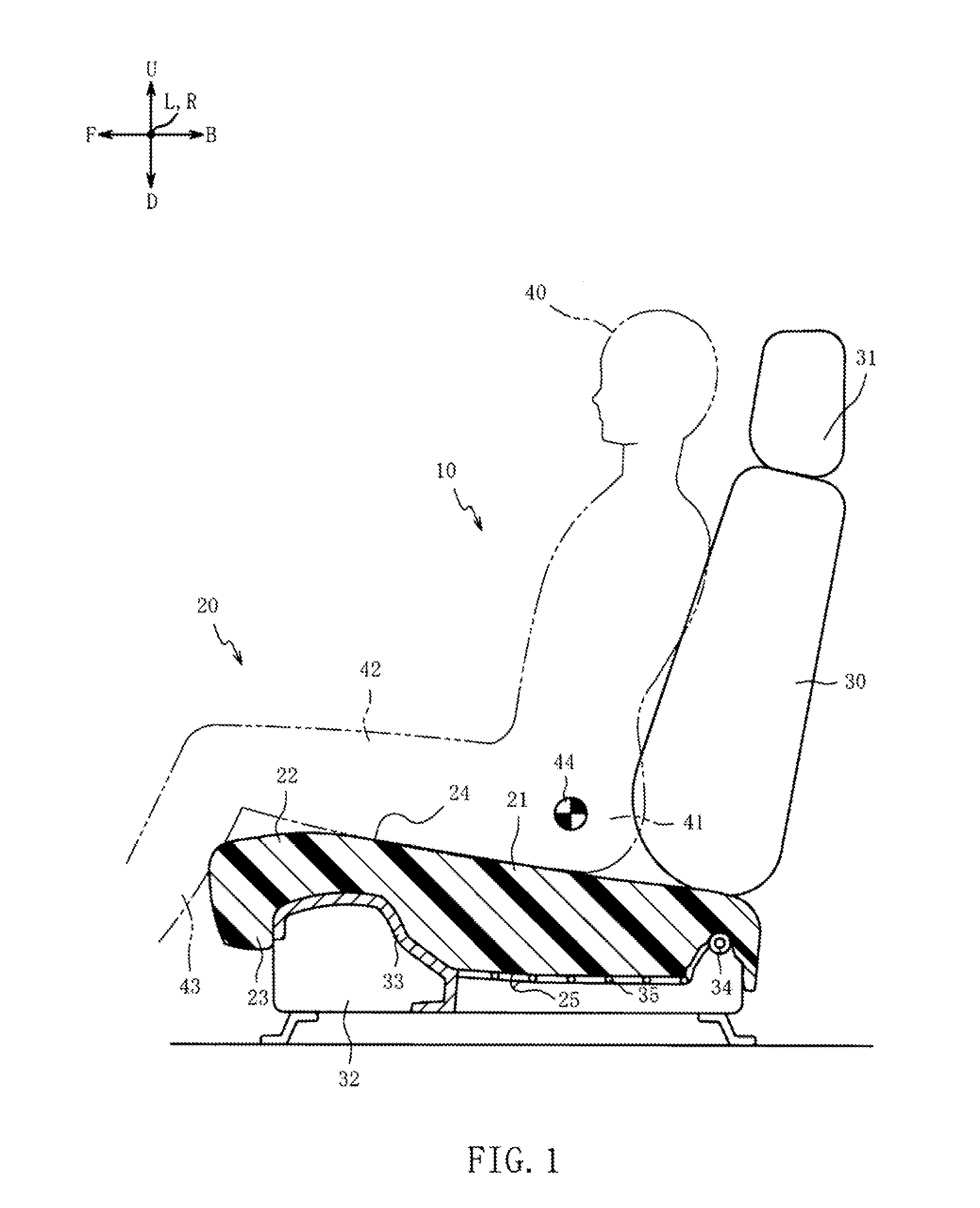
[0021]Hereinafter, a description will be given of preferred embodiments of the present invention with reference to the accompanying drawings. FIG. 1 is a partial cross-sectional view illustrating a partial cross section of a seat 10 on which a cushion pad 20 is mounted according to the present invention. Note that, the respective arrows U-D, L-R, and F-B in FIG. 1 denote the above-below direction, the right-left direction, and the front-rear direction of a vehicle (not shown) on which the seat 10 is mounted.

[0022]As illustrated in FIG. 1, the seat 10 includes: the cushion pad 20 (seat cushion); a seat back 30, which is tiltably coupled to the rear end portion of the seat cushion; and a head rest 31, which is coupled to the upper end portion of the seat back 30. The cushion pad 20 is the base material of the seat cushion on which a seated person 40 is seated, and is constituted by a foamed body such as flexible polyurethane foam. Note that, in FIG. 1, the illustration of the surface ...

second embodiment

[0079]While in the above-described second embodiment a description has been given of the case where the seating portions 71 and 81, the upper center portions 72 and 82, the lower center portions 73 and 83, and the bottom surface portions 74 and 84 are all formed with the flexible polyurethane foam (molded urethane) molded by the molding die in a predetermined shape, this should not necessarily be construed in a limiting sense. It is obviously possible to employ other materials. The other materials include, for example, slab urethane formed by cutting off the molded flexible polyurethane foam, chip urethane formed by crushing the listing and similar material generated in the manufacturing process of the flexible polyurethane foam, a three dimensional net-like body constituted of a plurality of three-dimensionally intertwined fibers made of synthetic resin, a fiber body such as solid cotton, a synthetic resin-made elastic body such as urethane rubber and thermoplastic elastomer. Lamin...


PUM


Abstract

[Problem]To provide a cushion pad that allows reducing the oppressive feeling in a thigh and the sinking of buttocks and improving the texture and the fit feeling.[Solution]In a portion positioned underneath a hip point of a seated person, an under-buttock portion is set to have a smaller force S25 during compression to 25% in a second portion including a seating surface than S25 of the first portion positioned on a bottom surface side. The thigh supporting portion is set to have smaller S25 of a portion including the seating surface than S25 of the first portion. This allows reducing the oppressive feeling in the thigh and the sinking of the buttocks and improving the texture and the fit feeling.

Description

TECHNICAL FIELD[0001]The present invention relates to a cushion pad, particularly, to a cushion pad that reduces an oppressive feeling in a thigh and sinking of buttocks.BACKGROUND ART[0002]A cushion pad used for, for example, a seat and a chair such as furniture equipped with transportation means such as a vehicle, a ship, and an aircraft includes: a thigh supporting portion, which supports the thigh of a seated person; and an under-buttock portion, which supports the buttocks of the seated person and receives a large load compared with the thigh supporting portion. When the hardness of the thigh supporting portion is set corresponding to the hardness of the under-buttock portion in the cushion pad, the thigh feels numbness, an oppressive feeling, a foreign-body feeling, and a resistance feeling (hereinafter, these are referred to simply as an “oppressive feeling”). On the other hand, when the hardness of the under-buttock portion is set corresponding to the hardness of the thigh s...

Claims


Application Information

Patent Timeline
IPC IPC(8): A47C7/24B61D33/00B64D11/06A47C7/18B60N2/64
CPCA47C7/24A47C7/18B61D33/0035B64D11/0647B60N2/646B60N2/70B60N2/7017B60N2/4263Y02T50/40
Inventor NAKADA, TORU
Owner TOKYO QUALITY ONE CORP
Learn More