Powered Shingle Remover

Inactive Publication Date: 2016-05-19
MCAFEE RONALD
View PDF6 Cites 2 Cited by
  • Summary
  • Abstract
  • Description
  • Claims
  • Application Information

AI Technical Summary

Benefits of technology

This patent describes a device for removing surface covering materials. The device has a blade that can be inserted between the covering material and a substrate. The blade is moved by an actuator that is controlled by a sensor. The sensor determines the resistance to continued movement of the blade and actuates the actuator to lift the blade away from the substrate. The device is supported on wheels and has a handle assembly for easy manipulation on the substrate. The blade is pivotably mounted on the head and the actuator causes pivotal movement of the blade. The device allows for efficient removal of surface covering materials without lifting forces affecting the operator.

Problems solved by technology

Roofs are used to protect the interior of a house and other structures from the external environment, and are subject to severe weather conditions.
However, these surface coverings have a limited lifespan, depending on the material used, and need to be replaced on a regular basis.
However, such methods are cumbersome and require a great deal of energy to be expended.
Moreover, the shingle itself may tear around the nail, particularly when the shingle has deteriorated with age, leaving the nail in the substrate.
However, the device requires manual operation by inserting the blade into engagement with the nails and pivoting to remove the shingles.
As the device needs to be carried at all times and requires a large amount of force to remove the nails it can be understood that it still requires significant manual labour to remove the shingles.
However all of these systems require manual actuation of the shingle removal system.
However, in this device the crank mechanism is continuously engaged, thereby consuming significant compressed air, which is used as the source of energy.
The mechanism for lifting the blade is very complex and because of the orientation of the blade and drive mechanism for the blade, creates recoil when in use.
Not only is this tiring, but the recoil poses a potential safety hazard when used on a roof.

Method used


Image

  • Powered Shingle Remover
  • Powered Shingle Remover
  • Powered Shingle Remover

Examples


Embodiment Construction

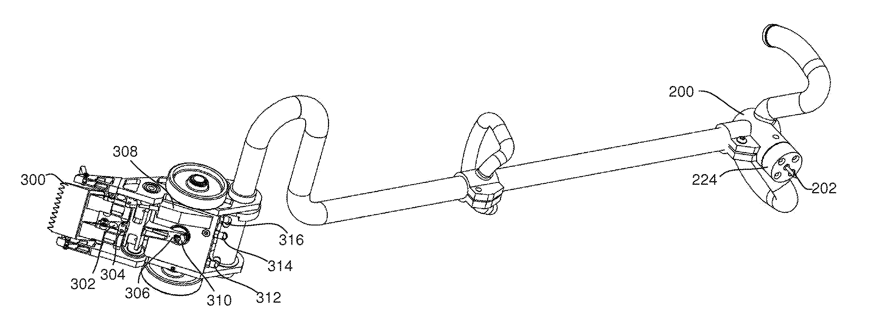
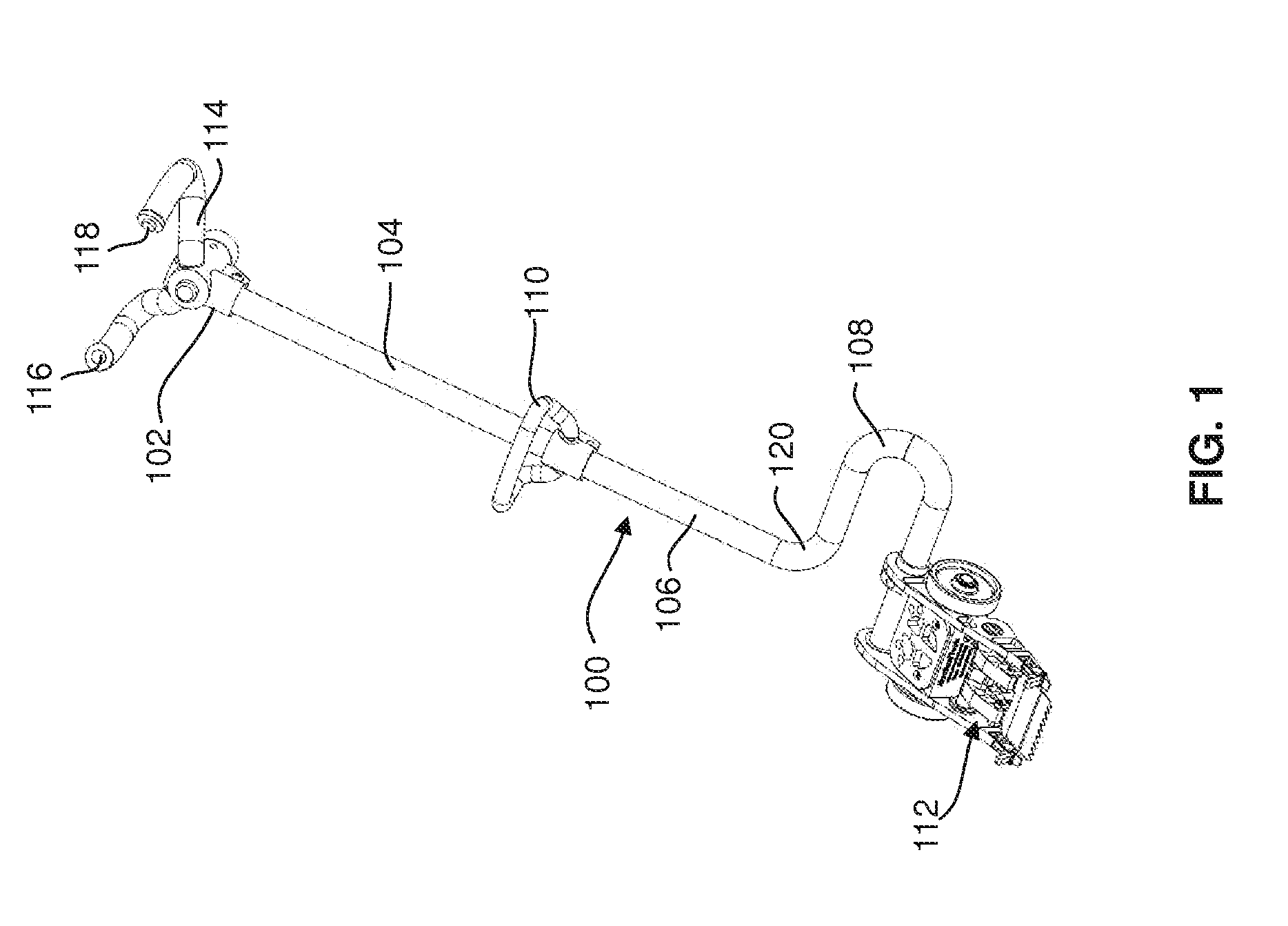
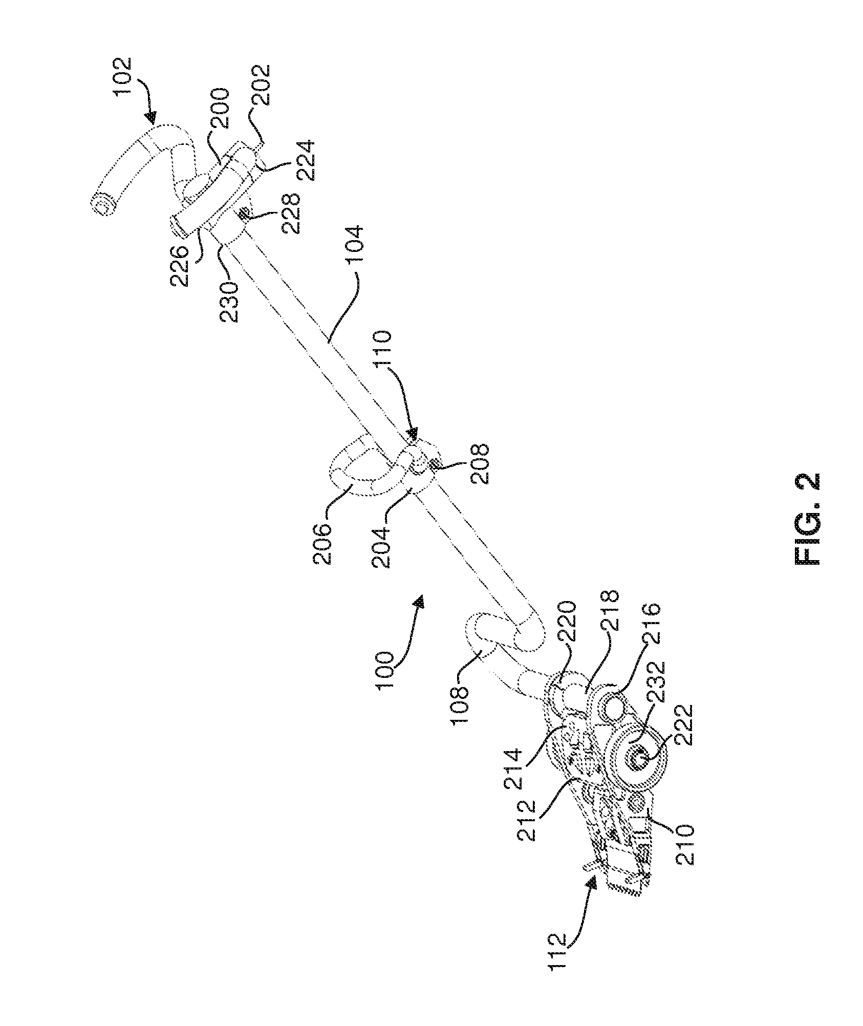
[0037]Referring initially to FIGS. 1 and 2, an exemplary embodiment of a device for removing a surface covering material from a substrate is shown. The device is referred to as a powered shingle remover 100. The remover 100 comprises a handle assembly 102 connected to a housing referred to as operating head 112. The handle assembly 102 includes an elongate shaft 104 with a linear, straight, section 106 terminating in a curved section 108. The linear section 106 of the shaft transitions into the curved section 108 through a plurality of elbows 120 to define a generally “C” shape lying in a transverse plane. Situated on the linear straight section 106 is a stabilising handle 110, whose position may be adjusted along the linear section 106 to suit the operator using the remover 100.

[0038]The handle assembly 102 terminates in a yoke 114 for primary control by the operator. A plurality of switches are located on the yoke 114 for access by the operator including a switch 116 for manual ov...


PUM


Abstract

A device used to remove surface covering materials such as shingles. The device is comprised of an end handle having a plurality of switches and an anchoring mechanism, a handle shaft with a straight and curved portion, a secondary handle, and a base assembly. The anchoring mechanism can be used to secure the device to its work surface. The base assembly provides the mechanisms to automate the removal of shingles or other surface covering materials fastened using fasteners such as nails. The base assembly includes a blade assembly, a rotary support, a lever, a piston assembly, and a switch valve. The switch valve controls the routing of the fluid supply connected to the device. The device is powered by a supply of air or other fluid from a source such as a compressor.

Description

CROSS-REFERENCE TO RELATED APPLICATIONS[0001]This application claims priority to U.S. Provisional Patent Application No. 62 / 079,904 filed on Nov. 14, 2014, entitled “Powered Shingle Remover” and the entire contents of which is incorporated herein by reference.FIELD OF THE INVENTION[0002]The present invention relates to a tool for use in removing surface covering materials, such as roof shingles.DESCRIPTION OF THE PRIOR ART[0003]Outdoor surfaces are exposed to weather conditions that vary around different times of the year. In many instances, these surfaces need to be covered to provide protection against the environment.[0004]One outdoor surface in particular need of protection is a roof. Roofs are used to protect the interior of a house and other structures from the external environment, and are subject to severe weather conditions. A roof typically has an external water repellent surface covering made from a material that provides a reasonable service life at a reasonable cost. On...

Claims


Application Information

Patent Timeline
IPC IPC(8): E04D15/00E04G23/00
CPCE04G23/006E04D15/003
Inventor MCAFEE, RONALDMORKUS, VACLAV
Owner MCAFEE RONALD
Why Eureka
Try Eureka