
Cyclic aperture flow regulator system

a flow regulator and cyclic aperture technology, applied in the field of surgery, can solve the problems of compromising the safety of the eye procedure, eye chamber instability, and eventual collapse of surrounding tissue, and achieve the effect of preventing post-occlusion instability of the body cavity and substantially reducing the cross-sectional area of the fluid apertur

Active Publication Date: 2016-05-12
ALCON INC
View PDF9 Cites 36 Cited by
  • Summary
  • Abstract
  • Description
  • Claims
  • Application Information

AI Technical Summary

Benefits of technology

The patent describes a device that prevents instability when surgically aspirating fluid and tissue fragments through a probe. It uses a flow regulator valve with an adjustable cross-sectional area to control the flow. The device helps to maintain a steady flow, even when the probe is blocked or the vacuum level is changed. This makes it easier to remove fluid and tissue fragments safely during surgery without causing any instability.

Problems solved by technology

This fluid surges, also known as post-occlusion surges, can lead to transient aspiration flow rates through opening of the distal end of the surgical probe can transitorily exceed the flow rate through the irrigation line thereby causing eye chamber instability and an eventual collapse of the surrounding tissue.
This instability and collapse can compromise the safety of the procedure of the eye, with potential undesirable damage to the posterior aspect of the lens capsule of the eye, and / or endothelium cells to be undesirably drawn away from the cornea and towards the distal end the tip of the handpiece.
On the other hand, too high an irrigation flow rate may undesirably move endothelium cells away from the cornea, or undesirably cause endothelium cells to be aspirated out of the eye.
Moreover, recent introduction of femtosecond laser assisted cataract surgery (FLACS) allows a laser induced significant softening of the lens material in many cataract procedures, making the use of ultrasonic energy unnecessary, only relying in aspiration of the laser-softened lens tissue material.
However, such higher vacuum exacerbate the surgical risks associated with post-occlusion fluid surges into the surgical probe.
The introduction of such amounts of irrigation fluid into the body can cause undesirable or excessive extravasation of irrigation fluid into the surrounding tissue.
Such post-occlusion surges can lead to transient aspiration flow rates through the hospital vacuum line that substantially exceed the flow rate of irrigation fluid and thereby cause a sub-ambient pressure to be momentarily applied to the surrounding tissue.
The momentary sub-ambient pressure condition may cause partial collapse of the body cavity, damage to tissue near the distal end of the aspiration tube, and / or undesired tissue or fluid to be drawn towards the distal end of the aspiration tube.
Therefore, prior art systems that use a venturi pump must operate modest vacuum levels, e.g. below 300 mmHg unless very small needle bores are used.
Such modest vacuum levels significantly limit the available un-occluded flow in such systems.
Therefore, such surge limiters are typically not used with peristaltic pumps that will significantly increase the pressure difference in response to an occlusion of the aspiration tip.
The absence of pressure rise in response to occlusion in the contemporary aspiration systems limits their ability to aspirate large tissue particles.
Also, an in-line surge limiter can undesirably reduce the maximum reflux flow rate.
In cataract surgery, for example, aspiration flow should be sufficient to quickly engage and aspirate lens particles from the eye, however in the event of an occlusion the high vacuum created in the aspiration line may temporarily produce too high a flow after the occlusion break which could collapse the eye and produce damage.

Method used


Image

  • Cyclic aperture flow regulator system
  • Cyclic aperture flow regulator system
  • Cyclic aperture flow regulator system

Examples


embodiment (

Alternative Embodiment (2)

Stand-Alone Flow Regulator System Embodiment

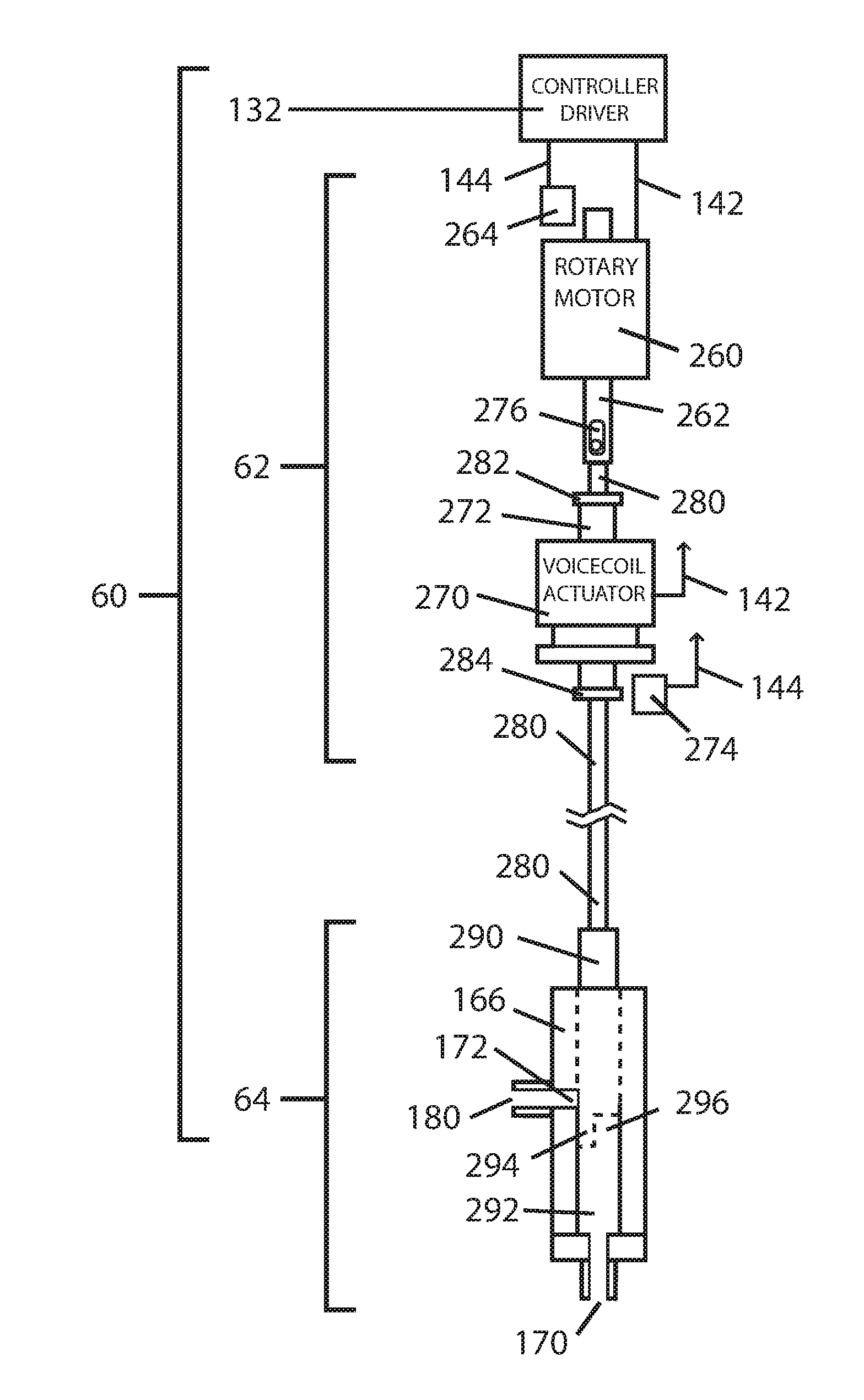
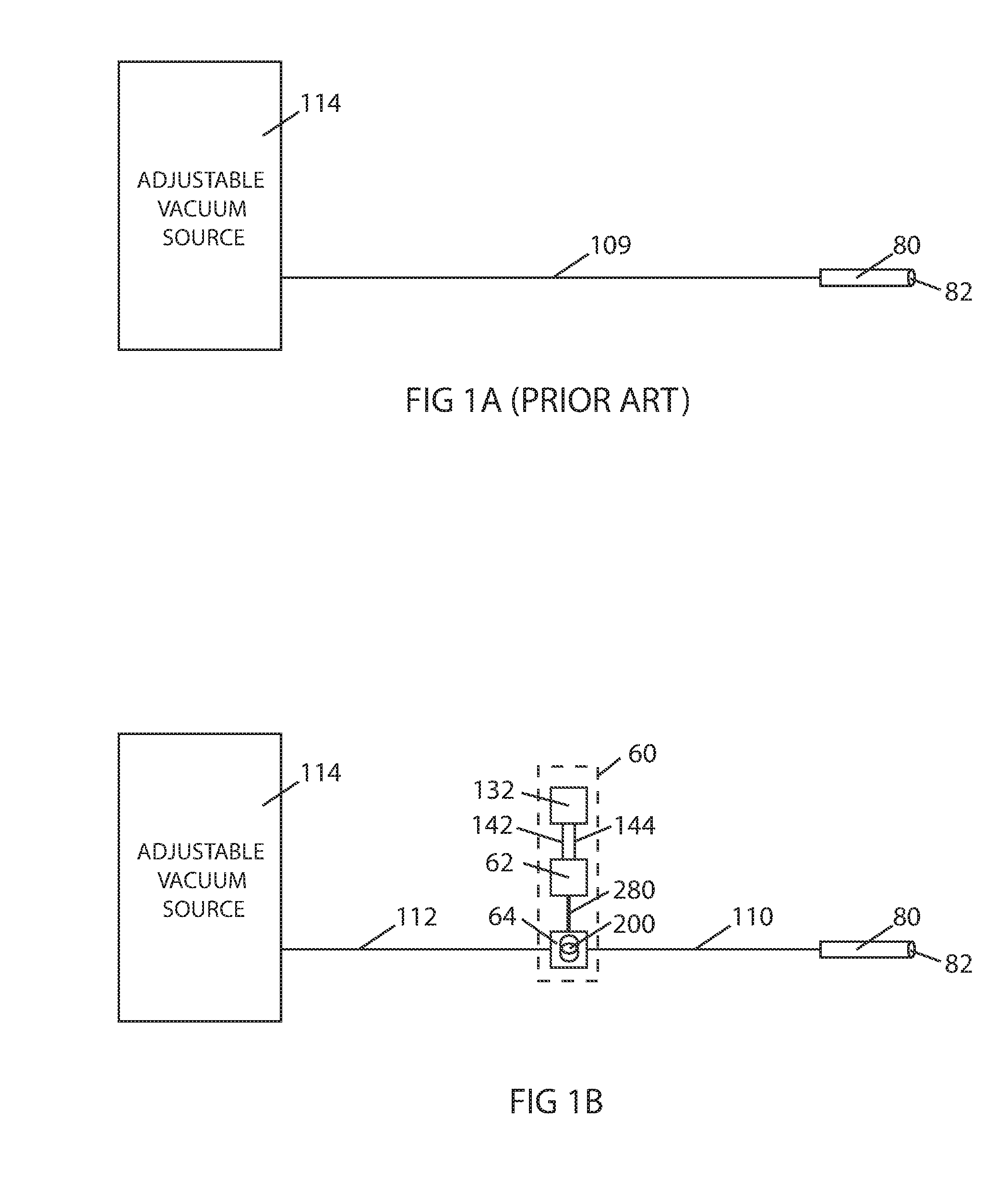
[0205]The cyclic aperture flow regulator system described in the preferred embodiment has an actuator portion 62 with sensors and actuators driven by a flow regulator controller 132 disposed in surgical console 150. Although this mode of operation allows the integration of multiple variables to improve system operation it is not a strict requirement for the implementation of this invention. Controller 132 including a processor and data storage memory can be incorporated in the same unit containing actuator portion 62 eventually requiring only external power such as a DC supply to operate in standalone mode. A user interface such as a footpedal 152 can directly connect to this standalone flow regulator system unit for an operator to command operation. The unit can further incorporate a vacuum sensor 140 in fluid connection with second fluid path 112 and disposed for example in the valve portion 64 of the flow regul...


PUM


Abstract

A cyclic aperture flow regulator system is disclosed to control flow exiting from a body cavity during surgery in a way that post-occlusion surges are effectively suppressed. The system is composed by an adjustable fluid aperture installed in a fluid path connecting the aspiration port of a surgical probe with a vacuum source, the probe to be inserted in a body cavity. The cross-sectional area of the fluid aperture can be modified by the action of an actuator portion driven by a controller. The controller commands the actuators in the actuator portion to modify the cross-sectional area of the adjustable fluid aperture in cycles. Each cycle of aperture dimension fluctuation includes at least one segment where the fluid aperture cross-sectional area is substantially reduced. The segment of each cycle where the cross-sectional area of the fluid aperture is substantially reduced can optionally include a transient complete closure of the aperture. The cycles of fluid aperture fluctuation are programmed to occur at a rate fast enough to produce a substantially steady flow, with minimum flow ripple and pressure ripple. Flow rate across the cyclic aperture flow regulator system is a function of the vacuum level of the vacuum source and can be regulated by adjusting the level of the vacuum. Flow rate across the cyclic aperture flow regulator system is also a function of the RMS value of the cross-sectional area of the fluid aperture and can be regulated by adjusting the amplitude of the waveform of each cycle.

Description

CROSS-REFERENCE TO RELATED APPLICATIONS[0001]This application claims the benefit of the following provisional patent applications filed by this inventor:[0002]1) USPTO Provisional Patent Application Ser. No. 61 / 830,792 filed Jun. 4, 2013[0003]2) USPTO Provisional Patent Application Ser. No. 61 / 897,827 filed Oct. 31, 2013BACKGROUND[0004]1. Field of Invention[0005]This invention relates to surgery, specifically to an improved flow regulation system that can be used with advantage in ocular surgery.[0006]2. Prior Art[0007]Various contemporary surgical procedures require aspiration of fluids that may contain solid or semi-solid tissue or other debris. In many cases, the fluids may need to be aspirated from a body cavity such as from within the lens capsule of the eye or a cavity in a joint such as the shoulder or the knee. It is typically desirable to maintain an ambient or a super-ambient pressure within the body cavity during such surgical procedures. For example, the lens of a human ...

Claims


Application Information

Patent Timeline
Patent Type & Authority Applications(United States)
IPC IPC(8): A61F9/007A61M1/00
CPCA61F9/00736A61M1/0035A61F9/00745A61M1/0066A61M2210/0612A61M1/0037A61M1/743A61M1/75A61M1/80A61M1/842A61F9/007
Inventor ZACHARIAS, JAIME
Owner ALCON INC
Learn More