
Surgical drill having a brake that, upon the drill bit penetrating through bone, prevents further insertion of the drill

Active Publication Date: 2016-05-05
STRYKER CORP
View PDF8 Cites 49 Cited by
  • Summary
  • Abstract
  • Description
  • Claims
  • Application Information

AI Technical Summary

Benefits of technology

This patent is for a surgical drill assembly that has a brake mechanism to prevent the drill bit from being inserted deeper into the bone. The assembly includes a handpiece with a motor and a chuck for holding the drill bit. A brake mechanism is connected to the case and includes a rack and a protector to surround the drill bit. An actuator is connected to the case and a plunger is connected to the actuator to engage or disengage the rack. A sensor is connected to the handpiece to monitor the motor or the drill bit. A controller is connected to the motor, actuator, and sensor and can engage or disengage the brake mechanism based on pre-determined settings or parameters. The drill assembly is designed for use with a bit assembly only includes a single piece drill bit.

Problems solved by technology

These fractures and breaks typically occur as a result of trauma to the bone.
This is because if the tip of the drill bit, presses through the bone, the tip could damage the soft tissue adjacent the opposite side of the bone.
This damage is more likely to occur if the tip, when pressed against the soft tissue, is rotating.
When at least one of the drills, typically the inner drill, completely penetrates the skull, the skull no longer offers resistance to the release action of the spring.
Owing to the tight fit of the drill bit in the bore, it is rather difficult to simply pull the bit out of the bone.
If a medical practitioner uses a large amount of manual force, there is the possibility that if they use this back force, especially if coupled with a back and forth prying action, can damage the bone.
This is why cranial perforators, while useful for preventing damage to the tissue underlying the bone against which they are pressed, have not proven particularly suitable for forming the relatively deep bores required by orthopedic surgeons.
Another problem with the use of cranial perforators is that during the formation of a bore, the drill bit may disengage from the motor before the bore is completely formed.
A limitation of this device is that it requires a bit assembly that includes inner and outer bits.
An additional issue faced by orthopedic surgeons is that it is difficult and time consuming during surgery to use the current depth gauges to determine the depth of a bone bore.
Unfortunately, if the surgeon's finger is placed incorrectly or slips, the measurement will be incorrect.
Also, when the hook extends through the bone bore and out from the bottom of the bore, adjacent tissues can be subject to damage.

Method used


Image

  • Surgical drill having a brake that, upon the drill bit penetrating through bone, prevents further insertion of the drill
  • Surgical drill having a brake that, upon the drill bit penetrating through bone, prevents further insertion of the drill
  • Surgical drill having a brake that, upon the drill bit penetrating through bone, prevents further insertion of the drill

Examples


Embodiment Construction

I. Handpiece

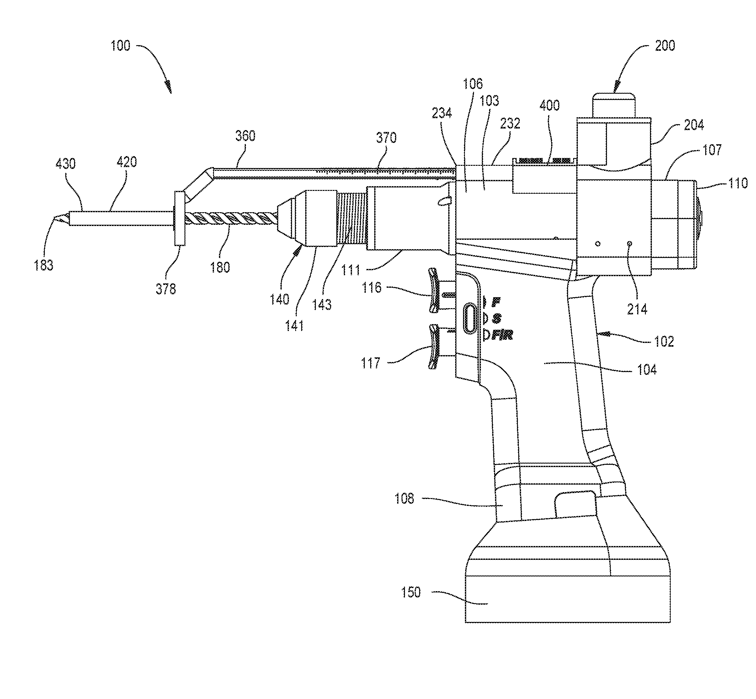
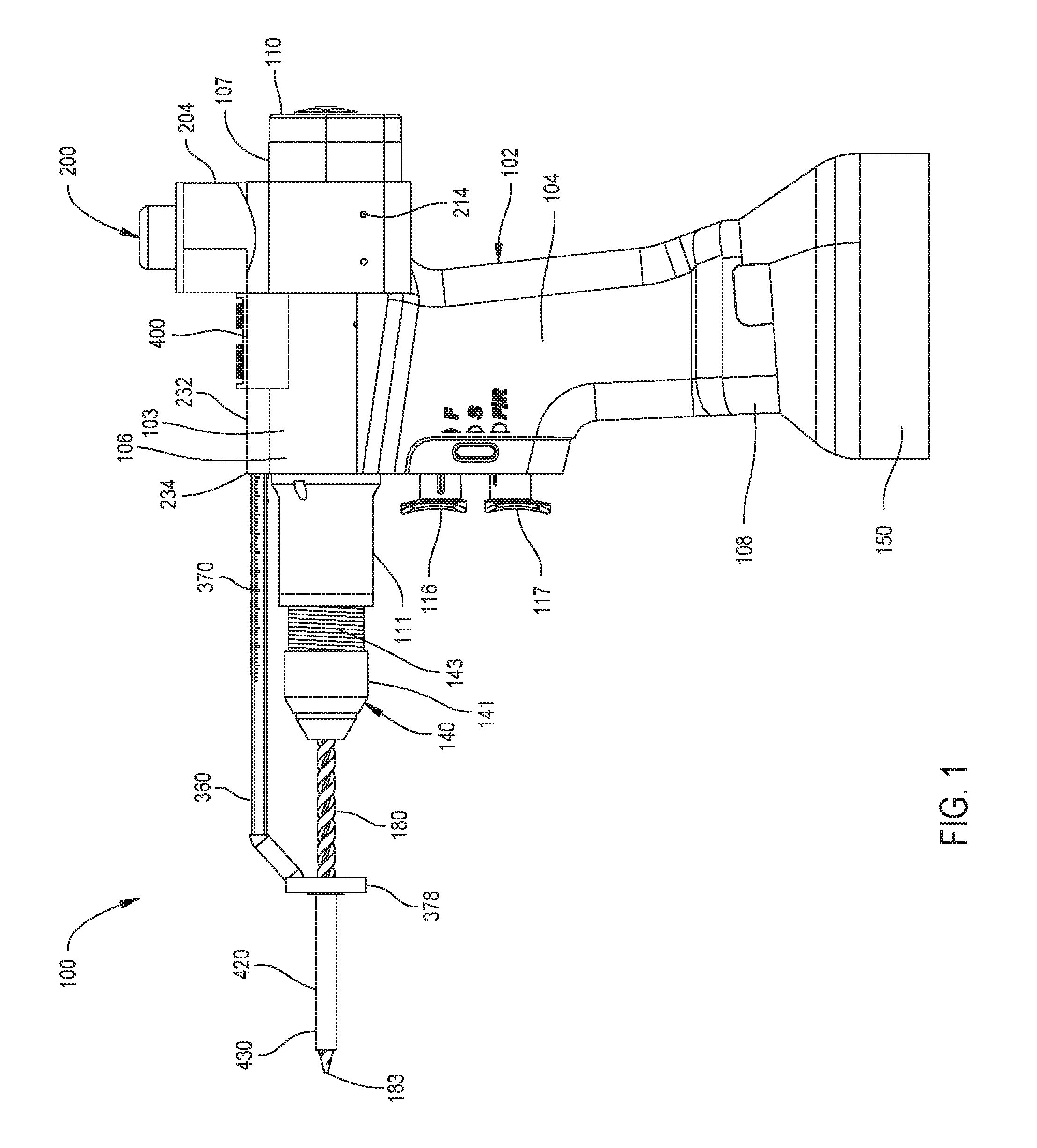
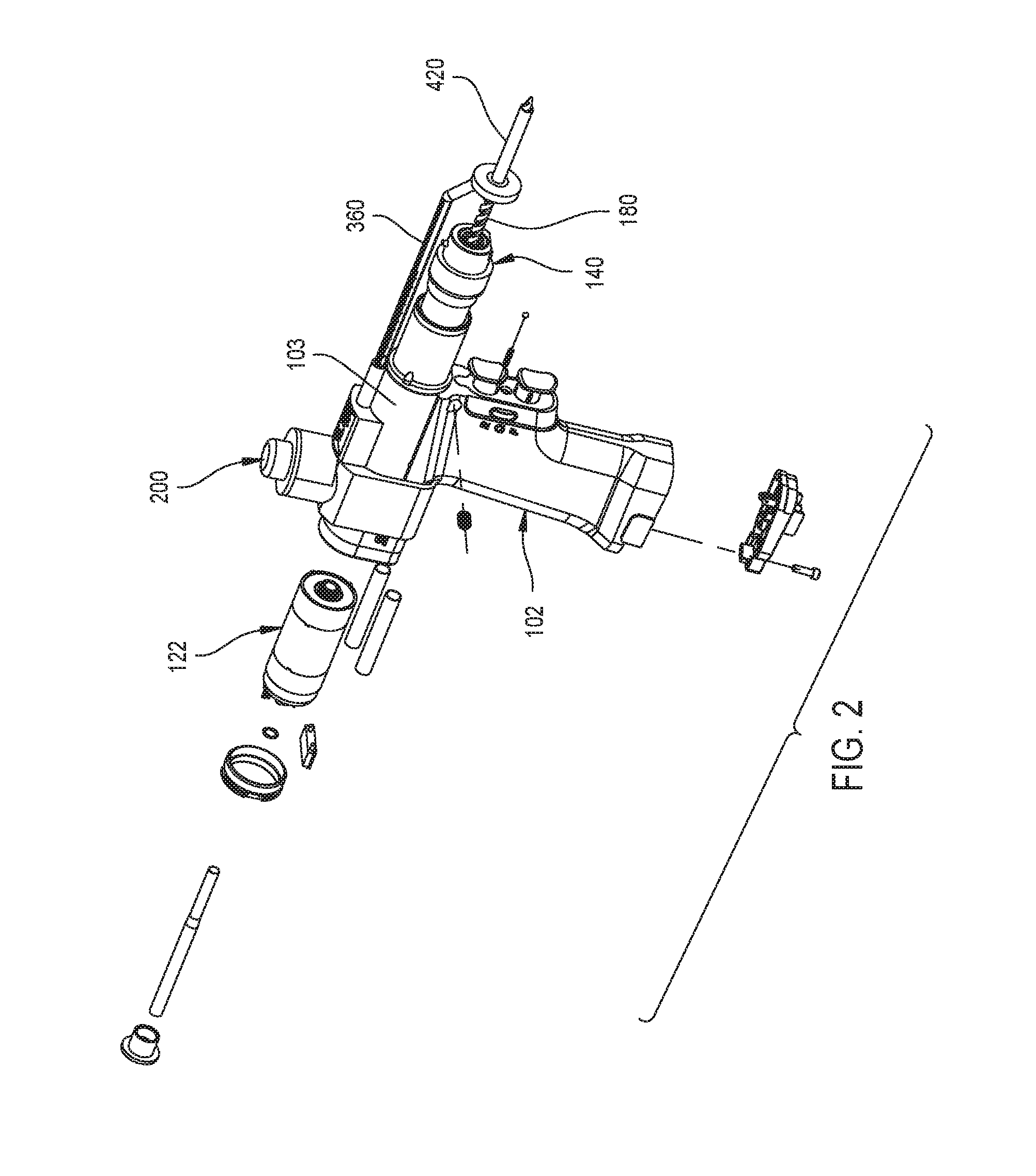
[0105]FIGS. 1, 2 and 3 illustrate a rotary surgical drill 100 in accordance with the present invention. Rotary surgical drill 100 comprises handpiece 102, chuck assembly 140, drill bit 180, controller 450 and brake mechanism 200.

[0106]Rotary surgical drill 100 includes a handpiece 102. Handpiece 102 has a case or upper housing 103 and a handle 104 that extends downwardly from the case or upper housing 103. Handle 104 is generally in the form of a pistol grip that can be grasped during use by a medical practitioner. Handle 104 has a lower end 108. The case or upper housing 103 is generally cylindrical in shape and has a distal end 106 and a proximal end 107. The case or upper housing 103 has an internal cylindrical shaped cavity 120. The upper housing 103 and handle 104 are formed from suitable materials such as metals.

[0107]In the discussion of surgical drill 100, “Distal”, it shall be understood means away from the practitioner holding the drill 100; towards the surgica...


PUM


Abstract

A surgical drill for use with a drill bit. The drill includes a handpiece with a motor and a brake mechanism. The brake mechanism is a sliding rack adjacent a first end and a second end with a stop adjacent the drill bit. An actuator is mounted to the handpiece and a plunger is coupled to the actuator. A sensor asserts a signal when the drill bit penetrates bone. When the sensor asserts the signal indicting the drill bit penetrated bone, the actuator moves the plunger into engagement with the rack to prevent further insertion of the drill bit.

Description

FIELD OF THE INVENTION[0001]This invention relates generally to surgical drills used to form a bore in a bone. More particularly, the surgical drill of the present invention has a brake mechanism that upon the drill bit penetrating through the bone, prevents further insertion of the drill bit.BACKGROUND OF THE INVENTION[0002]In modern surgery, one of the most important instruments available to medical personnel is the powered surgical drill. Typically, this drill comprises a housing in which a motor is secured called a handpiece. The motor has a shaft that is connected to some type of chuck or other coupling assembly that is mounted to the housing. The coupling assembly holds a cutting accessory that is applied to the patient in order to perform a specific medical procedure. Some common cutting accessories are drill bits, burs and reamers. These accessories are used to drill into and / or separate sections of soft tissue and hard tissue, commonly referred to as bone. The ability to us...

Claims


Application Information

Patent Timeline
IPC IPC(8): A61B17/16A61B90/00
CPCA61B17/1633A61B17/162A61B17/1624A61B17/1626A61B17/1628A61B2090/035A61B2017/0003A61B2017/00398A61B2017/00407A61B2017/0042A61B2017/00991A61B90/03A61B2017/00022A61B2017/00199A61B2090/036
Inventor XIE, MARK M.
Owner STRYKER CORP
Learn More