Blanking device for multi charged particle beams, and multi charged particle beam writing apparatus

a multi-charged particle and writing device technology, applied in the direction of beam deviation/focusing by electric/magnetic means, instruments, mass spectrometers, etc., can solve the problems of restricting the pitch of multi-beams, difficult to build a blanking circuit that can perform an operation of high speed and high precision, and complicated circuits

Active Publication Date: 2016-04-21
NUFLARE TECH INC
View PDF5 Cites 7 Cited by
  • Summary
  • Abstract
  • Description
  • Claims
  • Application Information

AI Technical Summary

Benefits of technology

The present invention provides a blanking device for multi charged particle beams that allows for individual and collective deflection of beams to control their exposure time. The device includes multiple individual blanking mechanisms and a common blanking mechanism with a plurality of electrode groups that can deflect the beams. The openings in the aperture member form multi beams, which can be selectively turned off or on using the individual and common blanking mechanisms. A limiting aperture member can block the off state of a beam. This invention enables precision in writing and exposure of target objects using multi charged particle beams.

Problems solved by technology

However, since the space for placing a circuit on a blanking plate and the amount of current to be used are restricted, there is no other alternative but to have an uncomplicated circuit for the amount of information of control signals.
Therefore, it has been difficult to build in a blanking circuit that can perform an operation of high speed and high precision.
Further, installing a blanking control circuit for each beam on a blanking plate restricts narrowing the pitch of multi-beams.
By contrast, when placing a control circuit for each beam outside the blanking plate and connecting them by wiring in order to secure a space for installing the circuit, since the wiring becomes long, there is a problem that crosstalk increases and writing precision degrades.

Method used


Image

  • Blanking device for multi charged particle beams, and multi charged particle beam writing apparatus
  • Blanking device for multi charged particle beams, and multi charged particle beam writing apparatus
  • Blanking device for multi charged particle beams, and multi charged particle beam writing apparatus

Examples


first embodiment

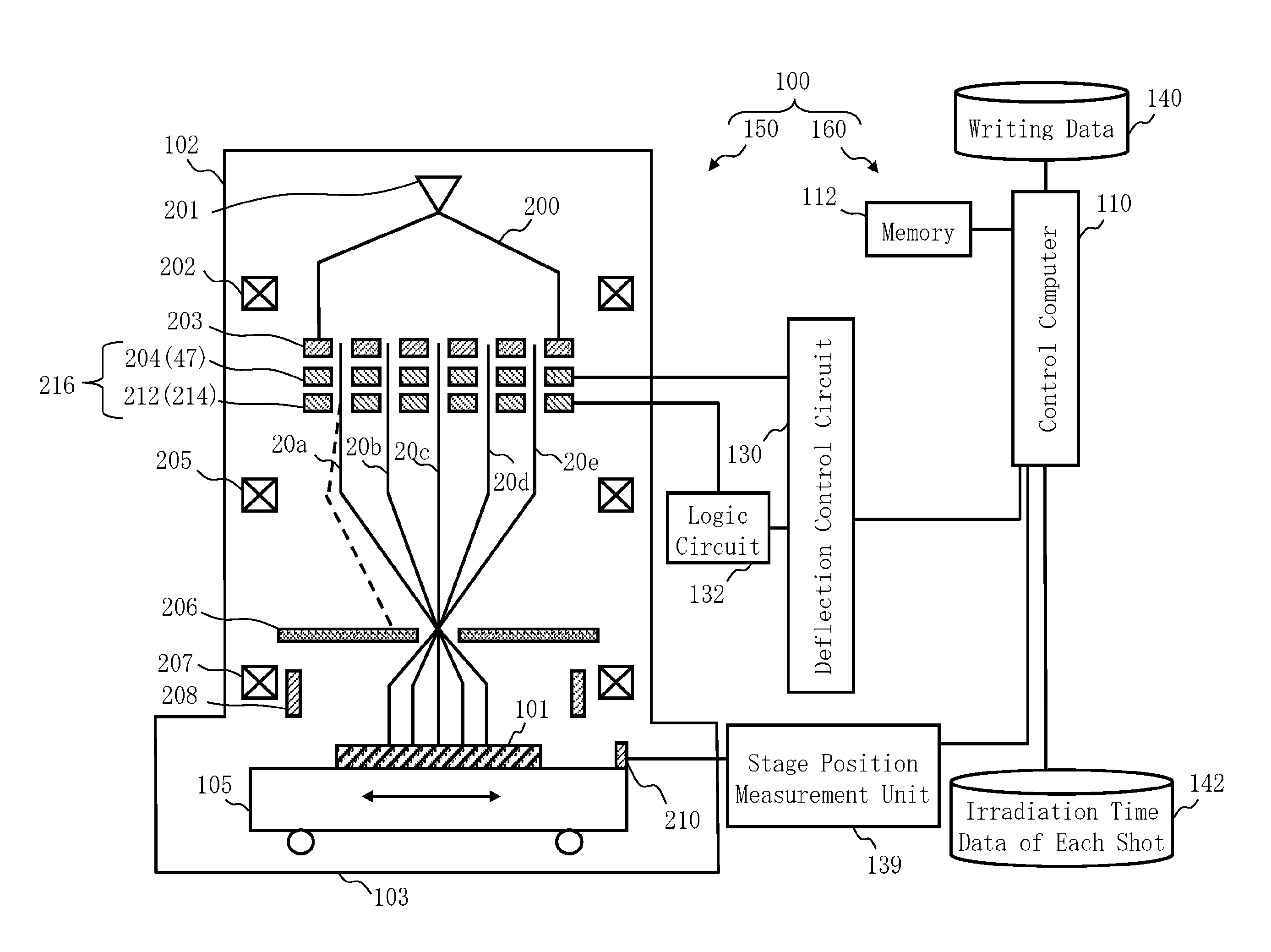
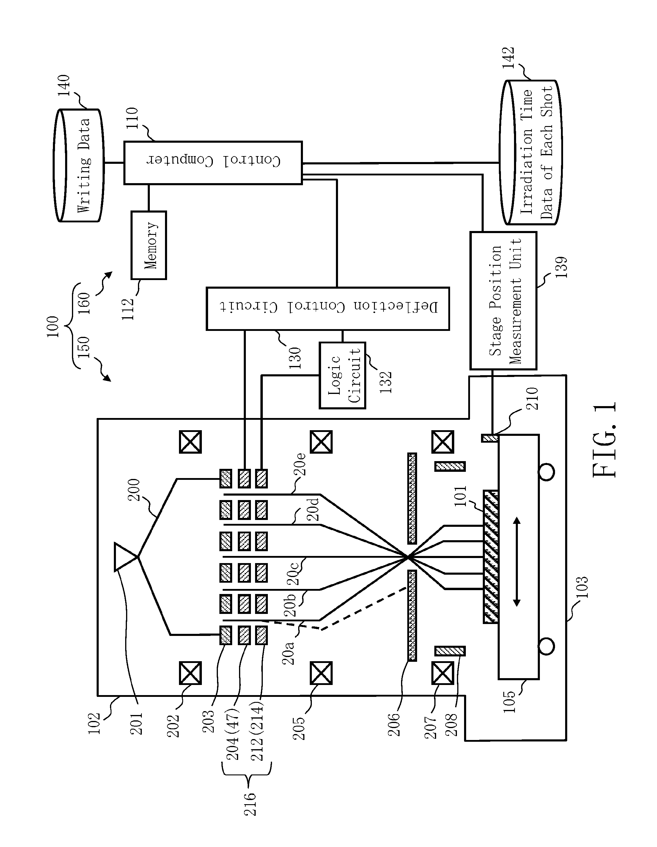
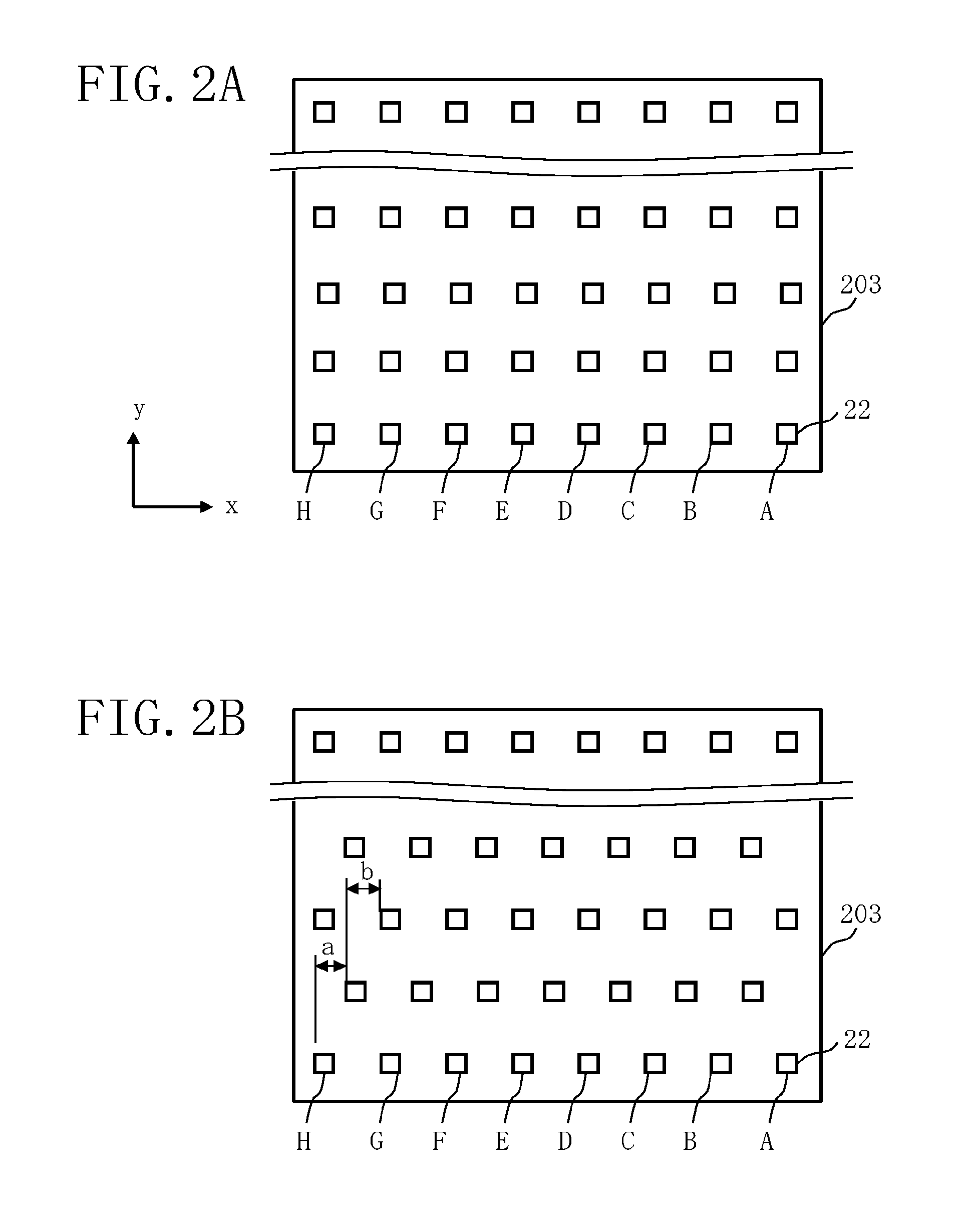
[0025]FIG. 1 is a schematic diagram showing a configuration of a writing or “drawing” apparatus according to the first embodiment. As shown in FIG. 1, a writing apparatus 100 includes a writing unit 150 and a control unit 160. The writing apparatus 100 is an example of a multi charged particle beam writing apparatus. The writing unit 150 includes an electron optical column 102 and a writing chamber 103. In the electron optical column 102, there are arranged an electron gun 201, an illumination lens 202, a multi beam forming plate 203, a blanking device 216, a reducing lens 205, a limiting aperture member 206, an objective lens 207, and a deflector 208. The blanking device 216 includes includes an individual blanking plate 204 and a common blanking plate 212. On the individual blanking plate 204, a plurality of individual blanking mechanisms 47 are arranged. On the common blanking plate 212, a common blanking mechanism 214 is arranged.

[0026]In the writing chamber 103, an XY stage 105...


PUM


Abstract

A blanking device for multi charged particle beams includes a plurality of individual blanking mechanisms configured to individually deflect a corresponding beam of multi charged particle beams so as to control ON / OFF of the corresponding beam, and a common blanking mechanism configured to include a plurality of electrode groups, each composed of facing electrodes, where an array pitch of a plurality of electrode groups is smaller than or equal to a pitch of the multi charged particle beams, and to collectively deflect the multi charged particle beams in order to control an exposure time.

Description

CROSS-REFERENCE TO RELATED APPLICATION[0001]This application is based upon and claims the benefit of priority from the prior Japanese Patent Application No. 2014-213099 filed on Oct. 17, 2014 in Japan, the entire contents of which are incorporated herein by reference.BACKGROUND OF THE INVENTION[0002]1. Field of the Invention[0003]Embodiments of the present invention relate generally to a blanking device for multi charged particle beams, and a multi charged particle beam writing apparatus, and more specifically, to a blanking device mounted in a multi-beam writing apparatus, for example.[0004]2. Description of Related Art[0005]The lithography technique that advances miniaturization of semiconductor devices is extremely important as a unique process whereby patterns are formed in semiconductor manufacturing. In recent years, with high integration of LSI, the line width (critical dimension) required for semiconductor device circuits is decreasing year by year. The electron beam writing...

Claims


Application Information

Patent Timeline
Patent Type & Authority Applications(United States)
IPC IPC(8): H01J37/147H01J37/317
CPCH01J37/3174H01J37/147H01J37/045H01J37/3177H01J2237/0435
Inventor MATSUMOTO, HIROSHI
Owner NUFLARE TECH INC
Why Eureka
Try Eureka