
Vehicle front structure

Inactive Publication Date: 2016-04-21
TOYODA IRON WORKS CO LTD
View PDF4 Cites 3 Cited by
  • Summary
  • Abstract
  • Description
  • Claims
  • Application Information

AI Technical Summary

Benefits of technology

The present invention relates to a vehicle front structure that can absorb impact energy and reduce occupants' injury values in the event of a collision. The structure includes an apron lower member that is designed in a crank shape and can deform in a Z-shape upon impact load from the front of the vehicle. The structure also includes an upper bent portion, an intermediate joint portion, and a lower bent portion that work together to form a front part, which is a low strength part that can deform upon impact. The front part is connected to the front side member through a joint member, which allows for proper absorption of impact energy and reduces the impact on occupants. The invention also includes a crash box that can absorb impact energy and properly align with the front side member to achieve proper absorption of impact energy in the event of a small overlap collision. The invention reduces the weight and cost of the vehicle front structure while still achieving effective impact absorption.

Problems solved by technology

In the conventional vehicle front structures, part of an impact load applied to the front side member upon collision is merely transmitted and dispersed from the apron lower member to the apron upper member, and reduction in collision impact or reduction in occupants' injury values upon collision cannot be sufficiently achieved, leaving room for improvement.

Method used


Image

  • Vehicle front structure
  • Vehicle front structure
  • Vehicle front structure

Examples


embodiment

[0030]An embodiment of the present invention will be described in detail below with reference to the accompanying drawings.

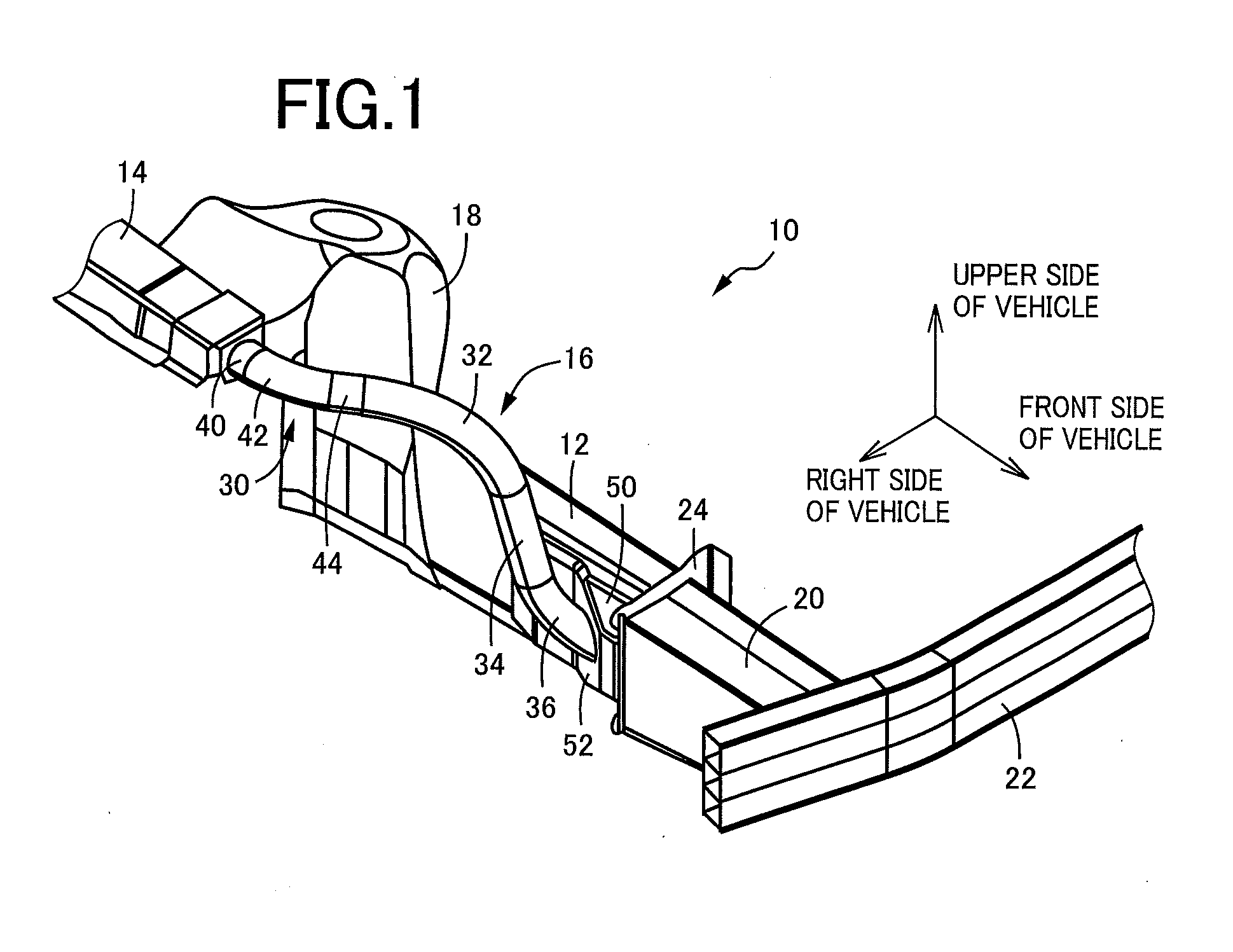
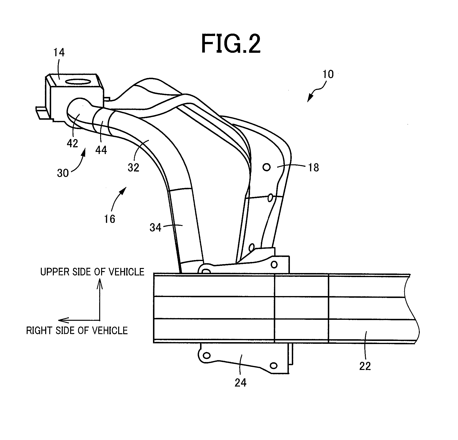
[0031]FIG. 1 is a schematic perspective view of a vehicle front structure 10 to which the present invention is applied. FIG. 2 is a front view of the vehicle front structure 10 as viewed from the front of a vehicle. FIG. 3A is a plan view of the vehicle front structure 10 and FIG. 3B is a side view of the vehicle front structure 10, which are shown associated with each other. This vehicle front structure 10 is used in the right front part of the vehicle, and a vehicle front structure for the left front part of the vehicle is configured to be a mirror image of the vehicle front structure 10. The vehicle front structure 10 includes a rectangular tubular front side member 12, an apron upper member 14, and an apron lower member 16. The front side member 12 is disposed in a right side part of the vehicle so as to extend in the longitudinal direction of the vehicle. T...


PUM


Abstract

A vehicle front structure including: a front side member in a side part of a vehicle that extends in a longitudinal direction; apron upper member above the front side member; and apron lower member that bridges between the upper member and a front end portion of the front side member. The lower member includes: a first end portion fixedly attached to the upper member and extending toward the front of the vehicle; an upper bent portion bent toward the bottom from the first end portion; an intermediate joint portion extending linearly from the upper bent portion toward the bottom; a lower bent portion bent toward the front from the intermediate joint portion, and the lower bent portion including a second end portion that is provided by a distal end portion of the lower bent portion, the second portion being fixedly attached to the front portion of the first side member.

Description

INCORPORATION BY REFERENCE[0001]The disclosure of Japanese Patent Application No. 2014-213230 filed on Oct. 17, 2014 including the specification, drawings and abstract is incorporated herein by reference in its entirety.BACKGROUND OF THE INVENTION[0002]1. Field of the Invention[0003]The present invention relates to vehicle front structures in which an apron lower member is disposed so as to bridge between an apron upper member and a front side member, and more particularly to a technique of reducing collision impact or reducing injury values upon collision.[0004]2. Description of the Related Art[0005]Vehicle front structures are proposed which include (a) a front side member disposed in a side part of a vehicle so as to extend in the longitudinal direction of the vehicle, (b) an apron upper member disposed above the front side member, and (c) an apron lower member disposed so as to bridge between the apron upper member and the front end of the front side member. The structure descri...

Claims


Application Information

Patent Timeline
IPC IPC(8): B62D21/15B62D25/08
CPCB62D25/08B62D21/152B62D25/082B62D25/088
Inventor SUZUMORI, MICHIO
Owner TOYODA IRON WORKS CO LTD
Learn More