
Injection device comprising a central rod movable in a cleaning position

Active Publication Date: 2016-04-21
DISCMA
View PDF0 Cites 10 Cited by
  • Summary
  • Abstract
  • Description
  • Claims
  • Application Information

AI Technical Summary

Benefits of technology

The invention is a machine for forming containers and includes an injection device that can be easily cleaned without having to disassemble the machine. The central rod in the injection device can be used for various purposes and functions and can be placed in a cleaning position to allow for easy cleaning without any parts being inaccessible to the cleaning products. The design of the injection device also reduces the excess volume of liquid and helps to prevent droplets from occurring when the injection device is removed from the container. The method for cleaning the injection device is simple and efficient and can be performed quickly.

Problems solved by technology

The stretch rod is therefore plunged in the preform and might contaminate it if not properly working in a contamination free environment and regularly being cleaned.
The housing is separated and isolated from the chamber, or injection nozzle, by fixed sealing means, meaning that, for properly cleaning the injection device and its stretch rod, the chamber and the housing have to be cleaned separately via two separate cleaning paths for the cleaning products, which complicates the injection device.
Furthermore, parts of the injection device remain difficult to clean, in particular around the fixed sealing means, without having to dismantle the injection device.

Method used


Image

  • Injection device comprising a central rod movable in a cleaning position
  • Injection device comprising a central rod movable in a cleaning position
  • Injection device comprising a central rod movable in a cleaning position

Examples


first embodiment

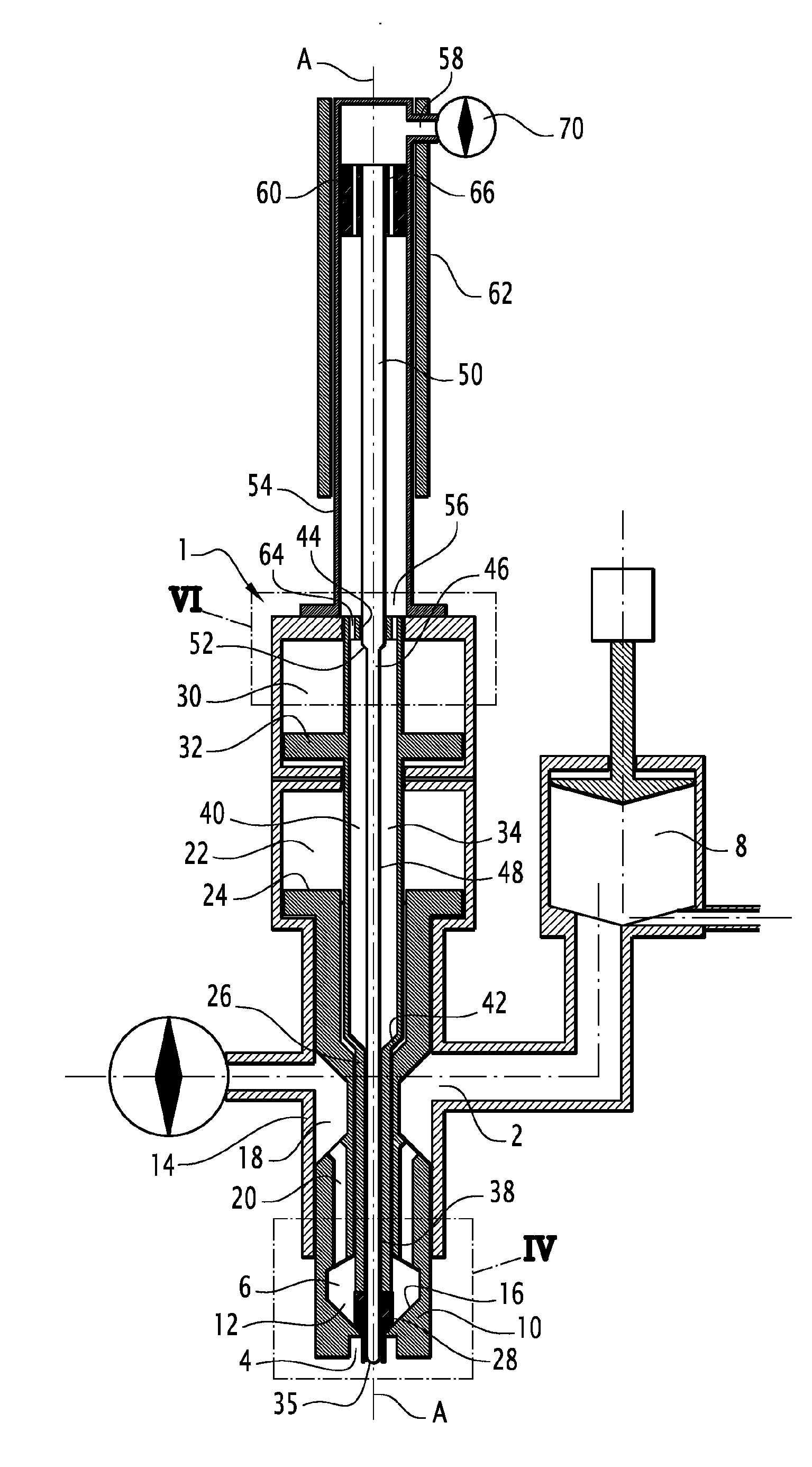
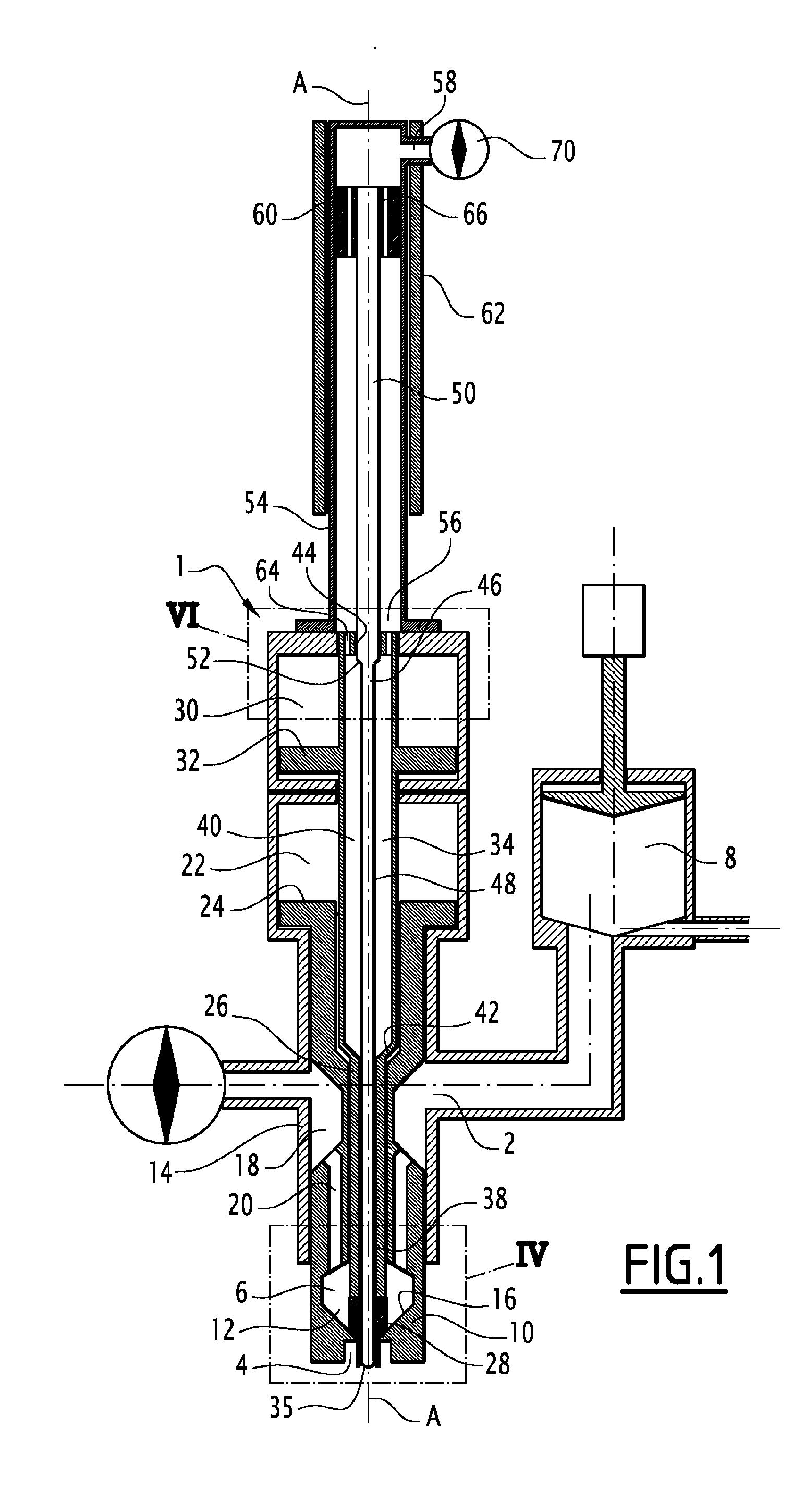
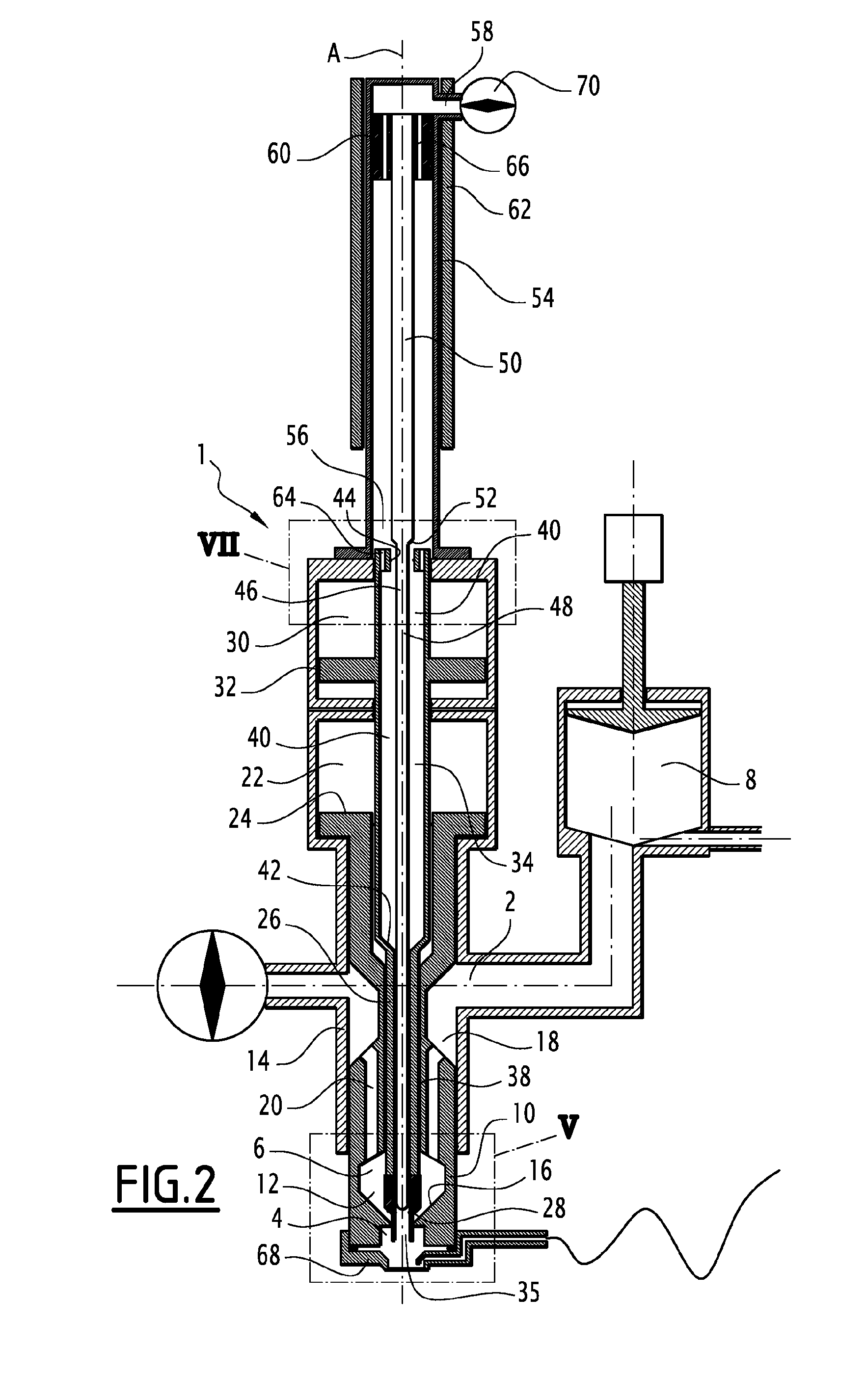
[0044]Referring to FIGS. 1, 2 and 4 to 7, there is described an injection device 1 according to the invention, intended to be used in a machine for forming containers, such as plastics bottles and similar, from preforms using liquid products, such as water or carbonated water based drinks or other products. Such machines, known as hydro forming machines, are known per se and will not be described in details here.

[0045]The injection device 1 comprises an inlet 2, an outlet 4 and a chamber 6 extending between the inlet 2 and the outlet 4 and placing the inlet 2 in fluidic communication with the outlet 4.

[0046]The inlet 2 is placed in fluidic communication with an incompressible liquid source (not shown), for example a water reservoir, via injection means 8 adapted for transferring the liquid from the liquid source to the inlet 2, and appropriate tubing extending between the inlet 2, the injection means 8 and the liquid source.

[0047]According to the embodiment shown in the figures, the...

second embodiment

[0074]In the second embodiment, the inlet 2 of the injection device is formed by the upper opening 58 of the housing 54, meaning that the upper opening 58 is connected to the injection means 8. The liquid injected through the inlet 2 reaches the chamber 6 via the duct 34 formed in the control rod 26, the control rod 26 comprising at least one opening 72 placing the duct 34 in fluidic communication with the chamber 6. The opening(s) 72 extend above the sealing area 36 of the duct 34 to prevent the liquid flowing through the duct 34 from exiting the duct 34 via its lower opening 35 in normal use of the injection device. It should be noted that, in this embodiment, the chamber 6 is formed only by its movable part 12. Since the liquid to be injected passes through the duct 34, the diameter thereof is arranged to have a proper flow of liquid, i.e. the diameter of the duct 34 is made larger outside the sealing are 36. In this case, more than one guiding portion 44 is provided inside the d...


PUM

PropertyMeasurementUnit
Fractionaaaaaaaaaa
Timeaaaaaaaaaa
Flow rateaaaaaaaaaa

Abstract

An injection device having an inlet for receiving a fluid, an outlet for injecting the fluid and a chamber therebetween. A hollow control rod is provided in the chamber and includes a duct extending through said control rod. A central rod extends in the duct and is movable between a retracted position and an active position. The central rod and the duct being arranged to prevent fluidic communication between the duct and the chamber when the central rod moves between its retracted and active positions. The central rod and the control rod are further movable relative to each other into a cleaning position, in which the duct is placed in fluidic communication with the chamber.

Description

CROSS-REFERENCE TO RELATED APPLICATIONS[0001]This application is the U.S. national phase of PCT Application No. PCT / EP2014 / 061167 filed on May 28, 2014, which claims priority to EP13305716.6 filed on May 30, 2013, the disclosures of which are incorporated in their entirety by reference herein.TECHNICAL FIELD OF THE INVENTION[0002]An injection device for injecting a liquid at an outlet of the device, of the type comprising:[0003]an inlet for receiving the fluid, an outlet for injecting the fluid and a chamber extending between the inlet and the outlet,[0004]a hollow control rod extending in the chamber and being movable between a sealing position, wherein the control rod closes the outlet, and an injection position wherein the control rod is arranged away from the outlet, the hollow control rod defining a duct extending through the control rod,[0005]a central rod extending in the duct of the control rod and movable between a retracted position wherein the central rod is at least in p...

Claims


Application Information

Patent Timeline
IPC IPC(8): B29C49/42B29C49/58B08B9/032B29C49/28
CPCB29C49/4273B29C49/28B29L2031/7158B08B9/0325B29C2049/5803B29C49/58B29C49/12B29C49/4289B29C49/46B29C2049/465B29C2049/5817B29C49/1232B29C49/42403B08B9/027
Inventor GILLET, DENIS
Owner DISCMA
Learn More