Observation apparatus
a technology of observation apparatus and a camera, which is applied in the field of observation apparatus, can solve the problem of little improvement in color reproducibility and other problems, and achieve the effect of improving color reproducibility
- Summary
- Abstract
- Description
- Claims
- Application Information
AI Technical Summary
Benefits of technology
Problems solved by technology
Method used
Image
Examples
first embodiment
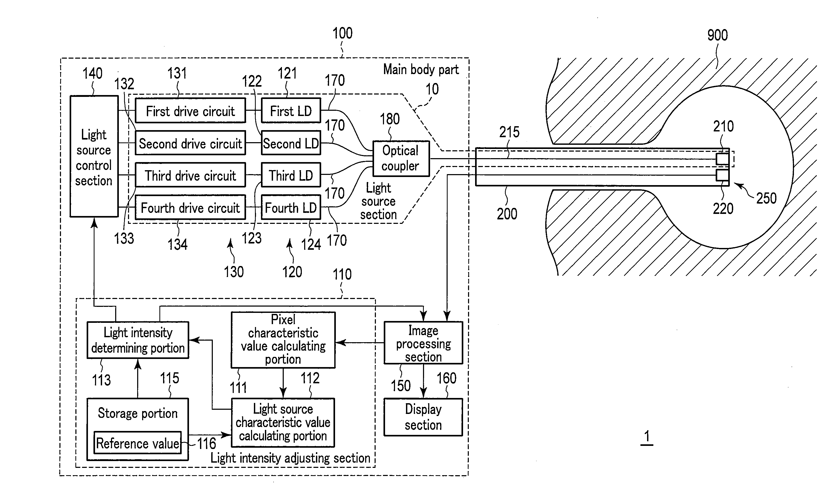
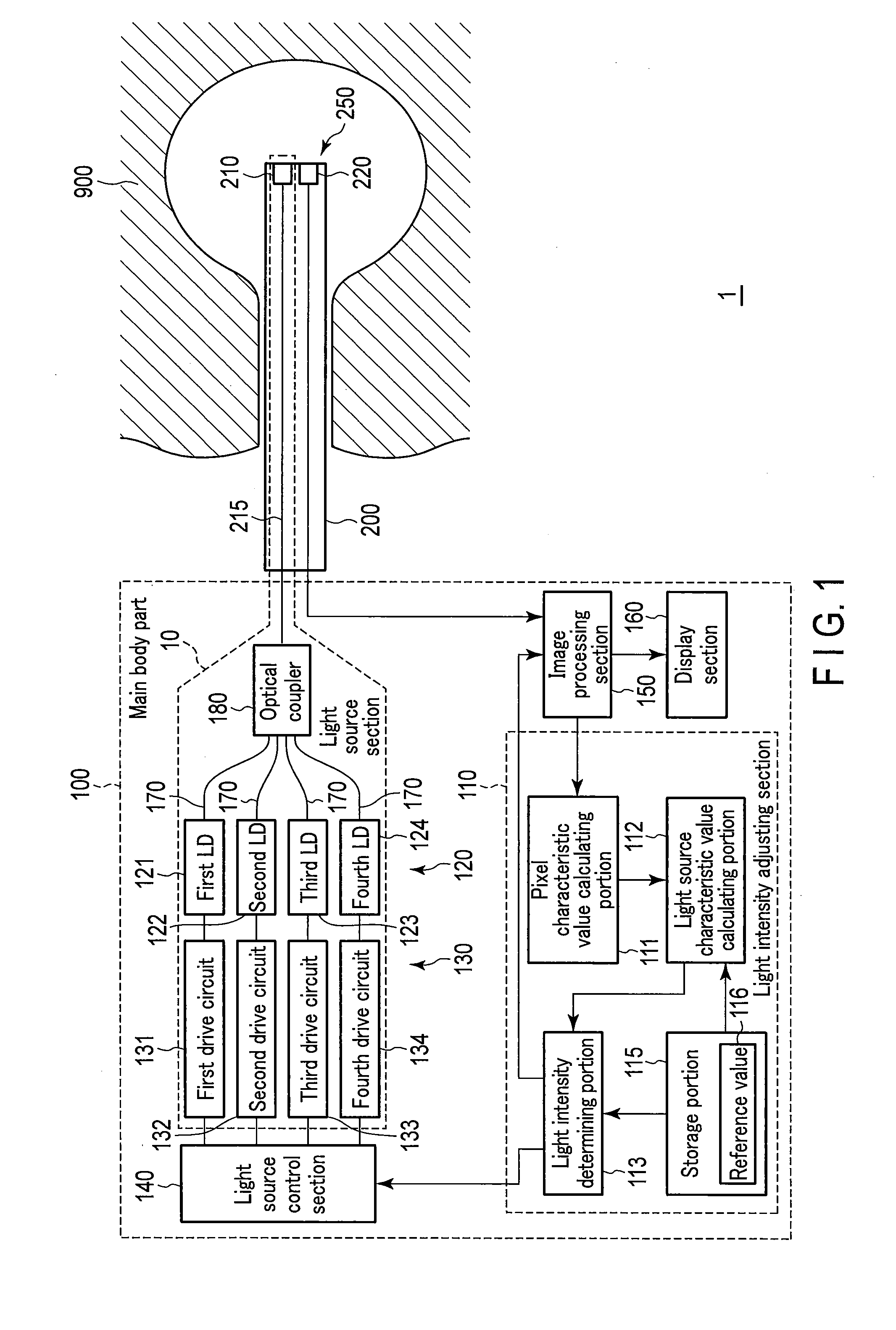
[0027]A first embodiment of the present invention will be described with reference to the drawings. FIG. 1 schematically shows a configuration example of an observation apparatus 1 according to the present embodiment. As show in FIG. 1, the observation apparatus 1 comprises a main body part 100 and an inserting part 200 to be inserted in a dark place where there is no light from outside. The observation apparatus 1 is an apparatus that images an object while emitting illuminating light from a distal end of the inserting part 200, for dark part observation.
[0028]The inserting part 200 has an elongated shape, and its one end is connected to the main body part 100. The one end of this inserting part on a side connected to the main body part 100 is referred to as a proximal end side, and the other end is referred to as a distal end side. At a distal end 250 of the inserting part 200, a light emitting section 210 and an imaging section (imager) 220 are disposed. The light emitting sectio...
second embodiment
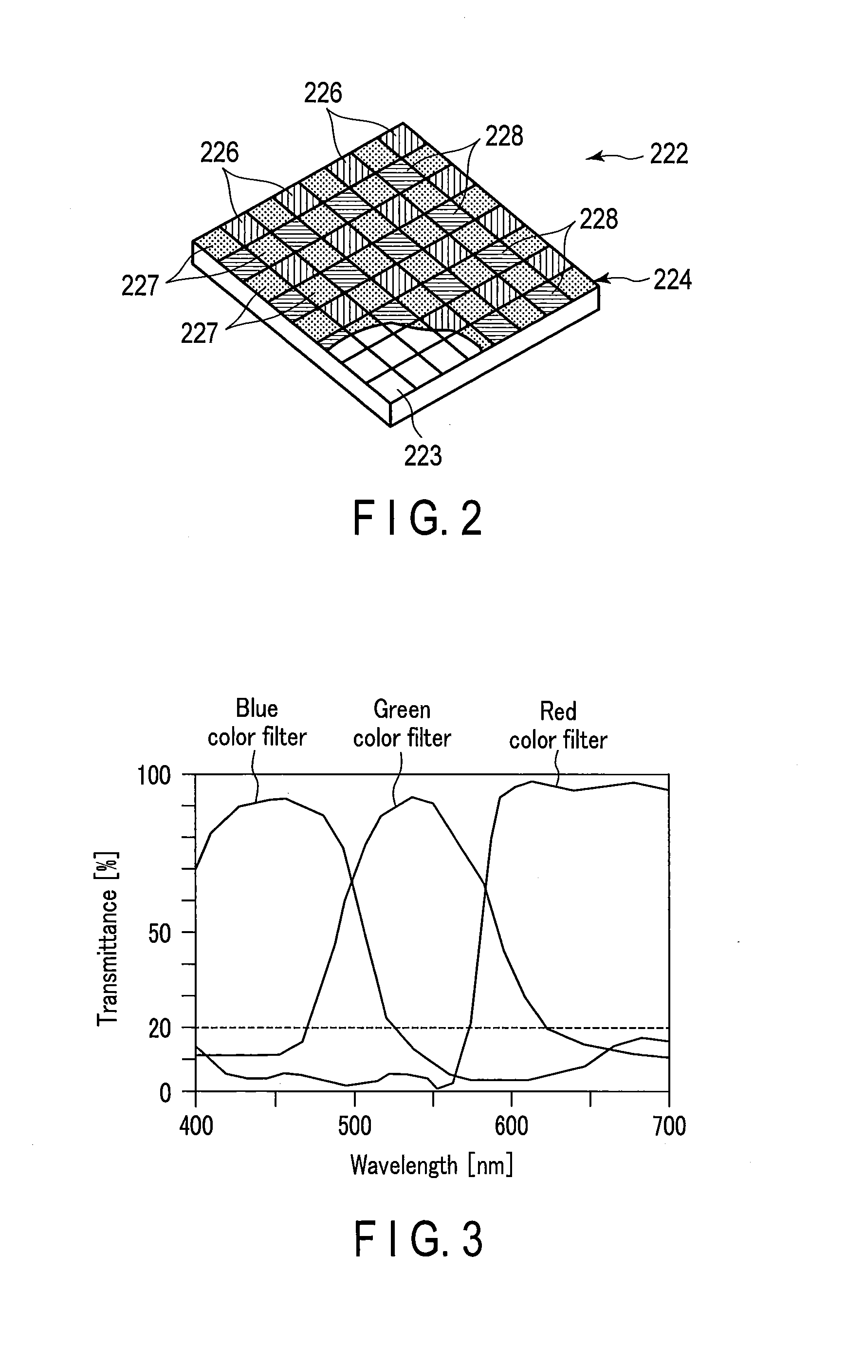
[0143]A second embodiment will be described. Here, different points from the first embodiment are described, and the same part is denoted with the same reference signs to omit the description. In the first embodiment, the R pixel average intensity, the G pixel average intensity and the B pixel average intensity which are the first characteristic values are adjusted to obtain the average value of the dynamic range of the image sensor 222. On the other hand, in the present embodiment, intensities of light transmitted through filters of respective colors of a color filter 224 are adjusted to the same value irrespective of the color, i.e., a wavelength region. Consequently, in the present embodiment, calculation in a light source characteristic value calculating portion 112 is different from that in the first embodiment.
[0144]Also in the present embodiment, similarly to the first embodiment, it is defined that a wavelength of a first semiconductor laser light source 121 included in a la...
third embodiment
[0168]A third embodiment will be described. Here, different points from the first embodiment are described, and the same part is denoted with the same reference signs to omit the description. In the first embodiment, the R pixel average intensity, the G pixel average intensity and the B pixel average intensity which are the first characteristic values are adjusted to obtain the average value of the dynamic range of the image sensor 222. On the other hand, in the present embodiment, table retrieval is performed on the basis of first characteristic values, and a light intensity ratio of each light source is adjusted. Here, a green color in which a sensitivity is high in human eyes is defined as a reference to determine a light intensity of each light source.
[0169]As shown in a schematic view of FIG. 13, a light intensity determining table 117 and a G pixel reference value 118 are stored in a storage portion 115 according to the present embodiment. As shown in FIG. 14, in the light int...
PUM
 Abstract
Description
Claims
Application Information
 - R&D
- Intellectual Property
- Life Sciences
- Materials
- Tech Scout
- Unparalleled Data Quality
- Higher Quality Content
- 60% Fewer Hallucinations
Browse by: Latest US Patents, China's latest patents, Technical Efficacy Thesaurus, Application Domain, Technology Topic, Popular Technical Reports.
© 2025 PatSnap. All rights reserved.Legal|Privacy policy|Modern Slavery Act Transparency Statement|Sitemap|About US| Contact US: help@patsnap.com


