
Fan holder for a fan, in particular of a switch cabinet

a fan and fan holder technology, applied in the direction of electrical apparatus, electrical apparatus, electrical apparatus contruction details, etc., can solve the problem that the main task is not the problem, and achieve the effect of reducing air throughput, improving air flow, and ensuring cooling

Inactive Publication Date: 2016-04-14
STEGO HLDG
View PDF9 Cites 21 Cited by
  • Summary
  • Abstract
  • Description
  • Claims
  • Application Information

AI Technical Summary

Benefits of technology

This patent describes a fan holder that can be used in a switch cabinet for improved cooling and protection against dust. The fan holder can be used with either a flap device or a filter insert, allowing users to choose between improved air circulation or improved dust avoidance. The fan holder includes a retaining device for easy installation and a fan funnel to ensure homogenization of the air stream. The technical effect is to provide a versatile and effective cooling solution for switch cabinets with improved air flow and protection against dust.

Problems solved by technology

The latter, however, is not the main task.

Method used


Image

  • Fan holder for a fan, in particular of a switch cabinet
  • Fan holder for a fan, in particular of a switch cabinet
  • Fan holder for a fan, in particular of a switch cabinet

Examples


Embodiment Construction

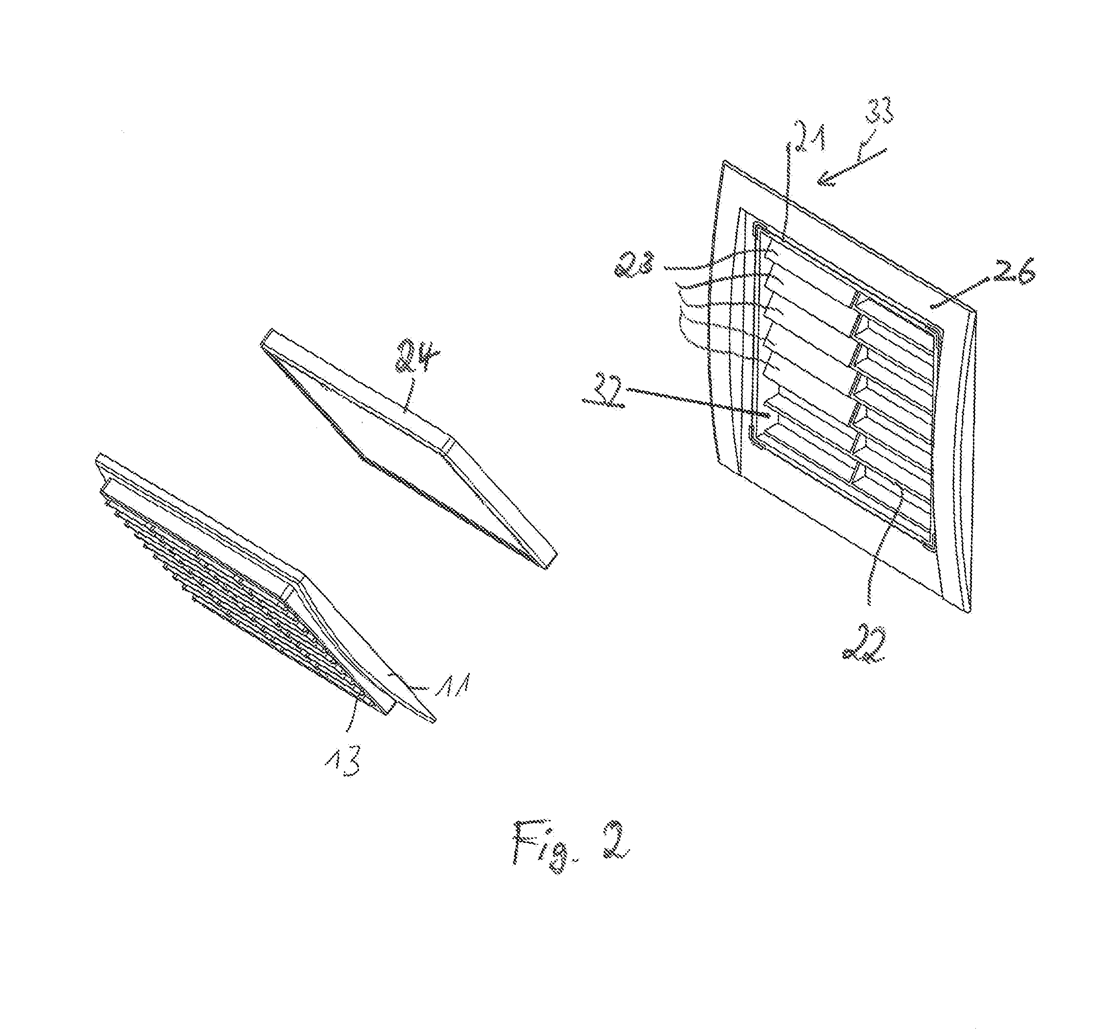
[0019]The following description uses the same designations for like, and like acting, parts. FIG. 1 shows a ventilating device comprising a fan holder 10 having a cover 11, which is closed off in the direction of an outer side 12 by a front lattice 13. In the direction of an inner side 14, the fan holder 10 is followed by a fan funnel 15. The fan funnel 15, in turn, is followed by a fan 16. The fan 16 may be designed, in particular, in the form of an axial fan.

[0020]In one use example, the ventilating device is connected to a switch cabinet (not shown). The ventilating device here is inserted into an aperture in a switch-cabinet wall and fixed there by a suitable fastening means, which is located in particular on the fan holder 10. The ventilating device thus establishes a connection between the interior of the switch cabinet and the outer region thereof. Depending on the direction of rotation of the fan 16 located in the switch cabinet, air can be taken into the switch cabinet, or ...


PUM

PropertyMeasurementUnit
retaining forceaaaaaaaaaa
elasticaaaaaaaaaa
pressureaaaaaaaaaa

Abstract

A fan holder for a fan includes a frame that has an opening through which a gaseous medium flows during operation. The opening forms an accommodating region that is designed to accommodate various replaceable inserts, in particular a filter insert and a flap device, and has at least one retaining device for fastening the particular insert.

Description

BACKGROUND OF THE INVENTION[0001]1. Field of the Invention[0002]The invention relates to a fan holder for a fan, in particular of a switch cabinet, and to a ventilating device, in particular for a switch cabinet, and to a set comprising a fan holder, at least one flap device and at least one filter mat.[0003]2. Discussion of the Related Art[0004]The prior art discloses fan devices comprising a fan holder and a fan, which is retained by the fan holder. In the case of such fan devices, cold air is taken in via a filter mat comparatively far down in the switch cabinet and is forced out via a (coarse) exit filter mat comparatively high up. This is intended to avoid the introduction of dust and to generate a positive pressure in the cabinet. The fans known in the prior art are considered to be comparatively ineffective and, in particular, not to be particularly variable.[0005]It is therefore an object of the invention to propose a fan holder, a fan device and a set comprising a fan holde...

Claims


Application Information

Patent Timeline
Patent Type & Authority Applications(United States)
IPC IPC(8): H05K7/20F04D29/70F04D29/52F04D25/08F04D19/00
CPCH05K7/20181H05K7/20172F04D29/703F04D19/002F04D29/522F04D25/08B01D46/0005F04D25/14H02B1/28H02B1/565H05K7/2019F04D29/4226
Inventor SCHANZENBACH, BERND ARMINDENT, ROBERTMANGOLD, ELMAR
Owner STEGO HLDG
Learn More