Fluid-Dynamic Bearing System

a bearing system and fluid-dynamic technology, applied in the direction of bearings, shafts, bearings, etc., can solve the problems of large diameters of recirculation channels, bearing systems cannot be filled with bearing fluid, and fluid can leak from bearing gaps and enter the motor cavity, etc., to achieve the effect of great structural heigh

Active Publication Date: 2016-04-14
MINEBEAMITSUMI INC
View PDF7 Cites 0 Cited by
  • Summary
  • Abstract
  • Description
  • Claims
  • Application Information

AI Technical Summary

Benefits of technology

The invention is a fluid-dynamic hearing system that reduces the risk of leakage of bearing fluid and minimizes power consumption. Structural height is increased while minimizing the diameter of the recirculation channel. Bearing fluid is circulated within the bearing system through recirculation channels formed by grooves in the components, such as the sleeve and hub. A pump seal and separator gap are used to further prevent leakage. Caps are used to add additional protection against leakage from the bearing gap. These features make the bearing system more efficient, durable, and reliable.

Problems solved by technology

The bearing described has the drawback that under the influence of external shocks or vibrations bearing fluid can leak from the bearing gap and enter into the motor cavity.
With greater structural heights, this can lead to relatively large diameters of the recirculation channels.
Furthermore, the design shown has the drawback that the bearing system can only be filled with bearing fluid after the covering caps have been mounted.

Method used


Image

  • Fluid-Dynamic Bearing System
  • Fluid-Dynamic Bearing System

Examples


Embodiment Construction

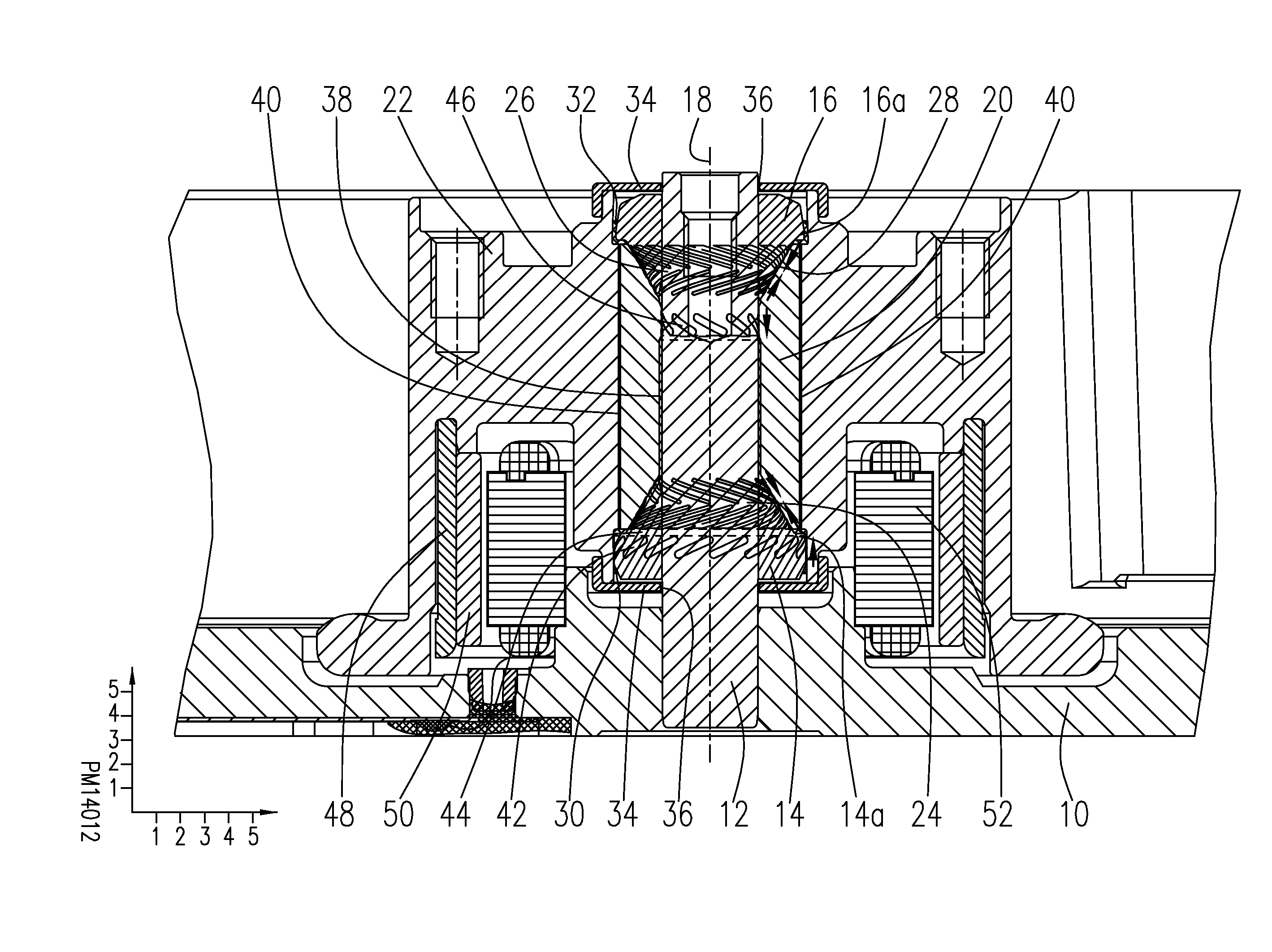
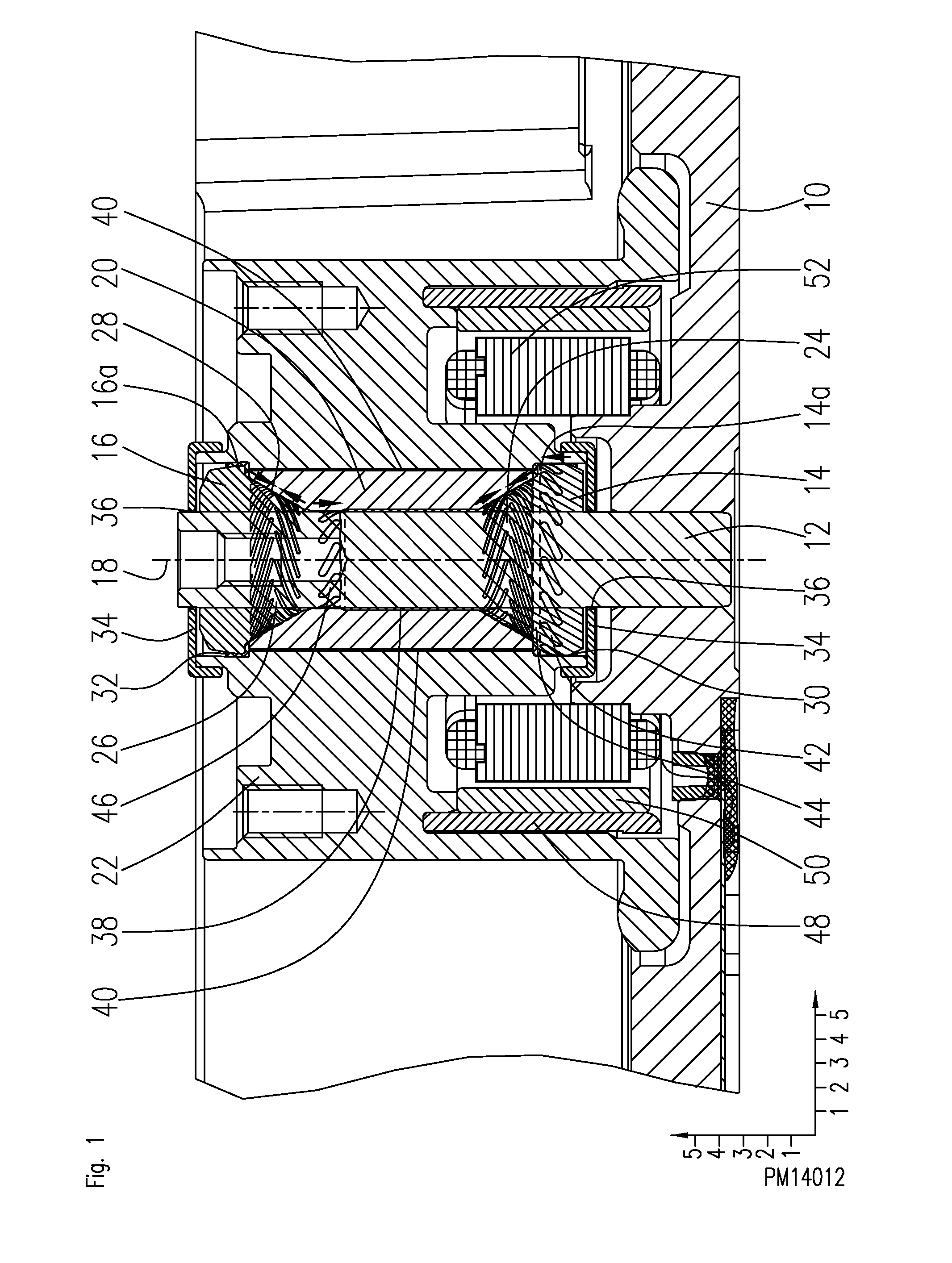
[0018]FIG. 1 shows a section through a spindle motor comprising a fluid-dynamic bearing system with two mutually symmetrical conical bearings.

[0019]A base plate 10 has a bore in which a fixed shaft 12 is arranged. On the shaft 12, two conical bearing components 14, 16, having conical bearing surfaces, are arranged at an axial distance from each other. The base plate 10, the shaft 12 and the two conical bearing components 14, 16 form the fixed component of the spindle motor. A sleeve 20 rotatable about a rotation axis 18 can be made of steel, for example, and comprises a bore as well as two end-side hollow conical recesses in which the shaft 12 and the two conical bearing components 14, 16 are received. The axial relative movement of the sleeve 20 with respect to the fixed component, the so-called axial play, can be between 10 and 20 μm, for example about 14 μm. A hub 22 can be made, for example, of aluminum and is joined to the sleeve 20 in an anti-rotation manner. The sleeve 20 and...


PUM


Abstract

The invention relates to a fluid-dynamic bearing system, in particular for the rotary support of a spindle motor, the bearing system comprising: a first conical bearing and a second conical bearing counteracting the first conical bearing, a fixed shaft along which the two conical bearings are arranged, a sleeve, a first and a second conical bearing component, which together with the sleeve form the first and second conical bearings, bearing structures applied to the sleeve and / or the conical bearing components, a bearing gap filled with a bearing fluid extending between the sleeve and the shaft and between the sleeve and the conical bearing components and sealed at each of its ends by a conical capillary seal, and a hub which rotates together with the sleeve about a rotation axis. The invention is characterized in that a pump seal is arranged between the first conical bearing and the adjacent capillary seal.

Description

FIELD OF THE INVENTION[0001]The invention relates to a fluid-dynamic bearing system, in particular a fluid-dynamic bearing system having two conical bearings.STATE OF THE ART[0002]Fluid-dynamic bearing systems are used, for example, for the rotary support of spindle motors or fans. The prior-art fluid-dynamic bearing systems comprise at least one fixed and at least one rotatable bearing component. The two bearing components comprise bearing surfaces characterized by bearing groove structures. The bearing surfaces are separated from each other by a bearing gap which is filled with a bearing fluid, such as bearing oil. In the operation of the bearing, the bearing groove structures generate a pumping action on the bearing fluid present in the bearing gap, thus building up a hydro-dynamic pressure within the bearing gap which gives the bearing its load bearing capability. There are fluid-dynamic radial bearings, fluid-dynamic axial bearings, and fluid-dynamic conical bearings. While the...

Claims


Application Information

Patent Timeline
Patent Type & Authority Applications(United States)
IPC IPC(8): F16C32/06H02K7/08
CPCF16C32/0662H02K7/086F16C32/064
Inventor BRUCKHOFF, MICHAELKIRCHMEIER, TOBIASWINTERHALTER, OLAFKULL, ANDREASHOFFMANN, JORG
Owner MINEBEAMITSUMI INC
Why Eureka
Try Eureka