
Method and System of Compressing Gas With Flow Restrictions

Active Publication Date: 2016-04-14
CARNOT COMPRESSION INC
View PDF7 Cites 9 Cited by
  • Summary
  • Abstract
  • Description
  • Claims
  • Application Information

AI Technical Summary

Benefits of technology

The present invention relates to a method and apparatus for compressing gas. The invention involves using a unique design to allow for unidirectional flow of emulsion in the compression tubes, which increases the flow rate and productivity of the gas compressor. The inventive method includes checking and enforcing distal emulsion flow, tapping the tube diameters, and adding bent end compression tubes. The invention also restricts flow in the capillary passages by using various valves or narrowing the physical size of the capillary passages to promote unidirectional flow and compress the entrained bubbles as they move radially outward. The invention results in significantly increased compressor efficiency and production.

Problems solved by technology

The efficiency of prior art commercial gas compressors is poor primarily because practicalities require that the gas be compressed rapidly.
Rapid compression makes it nearly impossible to dissipate the heat of compression during the compression process.
However, most compressed gas is stored in an uninsulated pressure vessel and the time between the compression of the gas and the use of the gas makes retention of the heat in the gas impractical.
Therefore, this 50-100% additional work to overcome the C-heat while compressing the gas is lost or wasted.
Historically isothermal compression has been impractical or impossible to achieve because the C-heat removal from the compressed gas requires too much time and / or additional energy for practical use.
However the manner in which Hughes creates a bubble train results in much longer and larger bubbles—with correspondingly greater bubble buoyancy—such that it is very difficult to force the bubbles towards the distal end of the compression tube.
Although Hughes' shroud acts as a seal by throwing the gas-liquid mixture at the radially remote inboard walls, the shroud design does not act as a rectifying agent to force unidirectional distal flow of entrained bubbles.
Hughes's shroud design also does not provide a pressurized gas storage housing and a gas / liquid separation chamber.
Hughes also does not disclose a method of recovering the kinetic energy imparted to the water by the impeller, therefore the gains of isothermal compression would be wasted on the energy imparted to the water.

Method used


Image

  • Method and System of Compressing Gas With Flow Restrictions
  • Method and System of Compressing Gas With Flow Restrictions
  • Method and System of Compressing Gas With Flow Restrictions

Examples


Embodiment Construction

[0048]The present invention relates to a method of compressing gas in an emulsified liquid—gas mixture and a centrifugal gas compressor. Similar numerals designate similar items throughout the specification and the drawings.

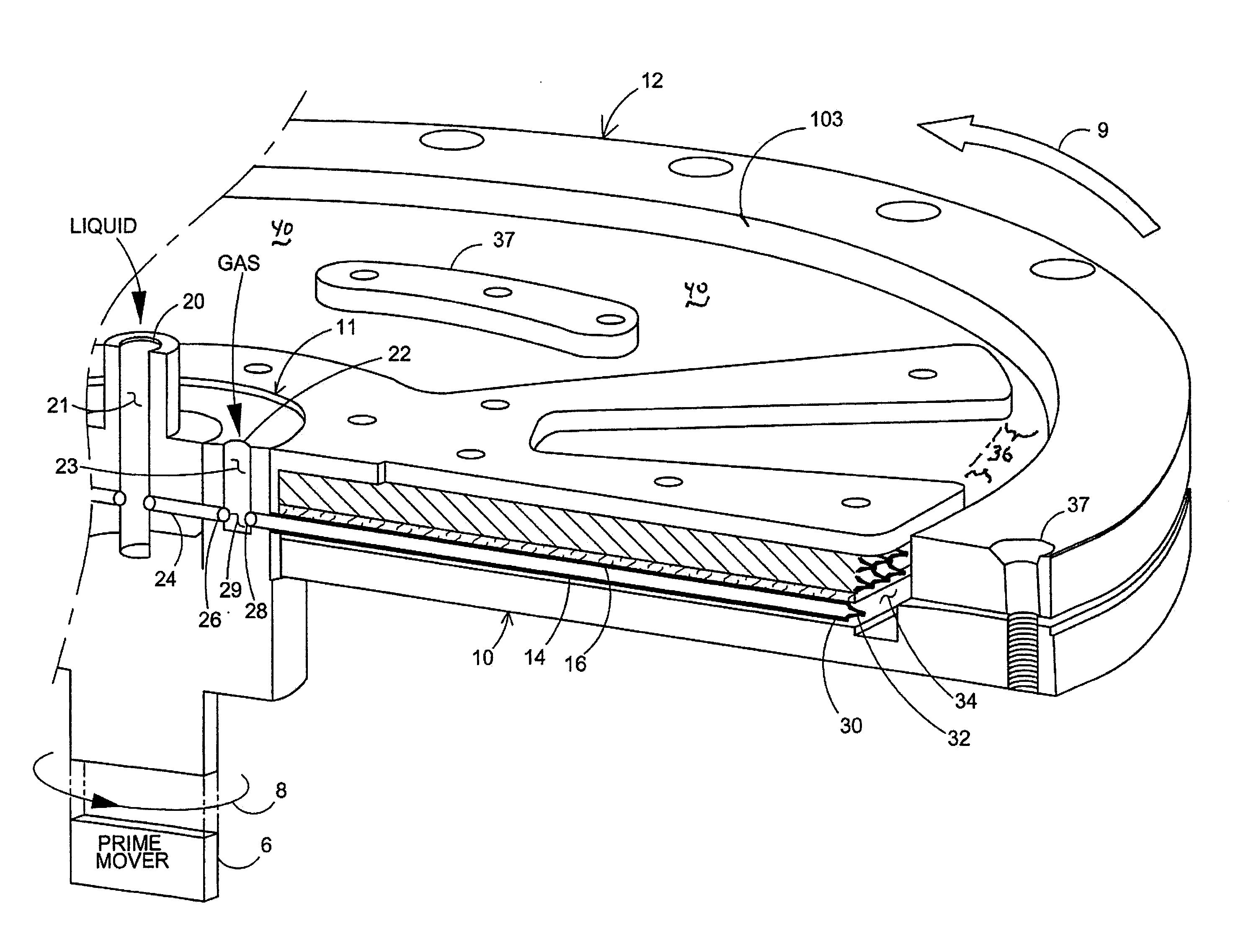
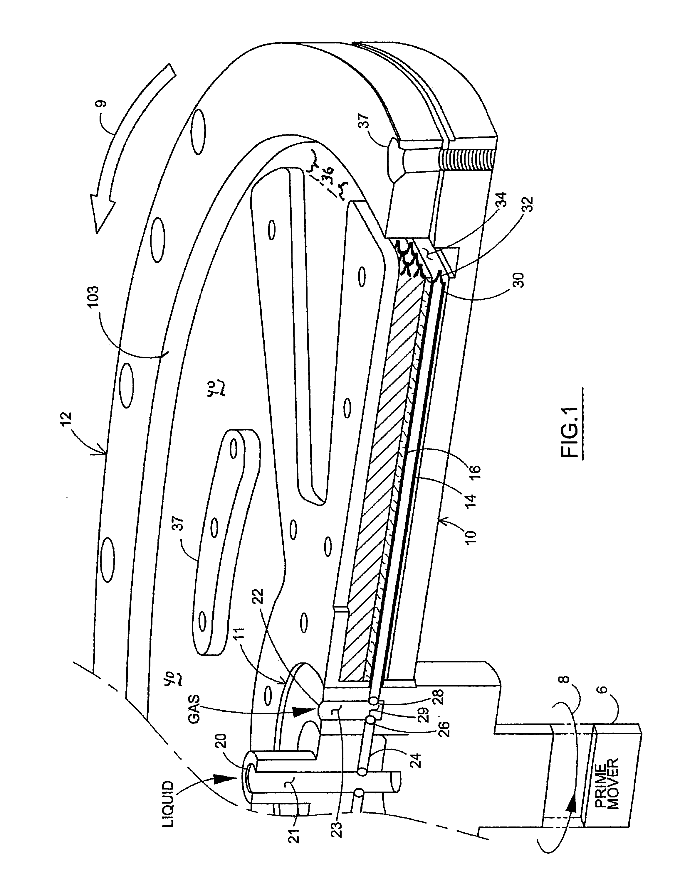
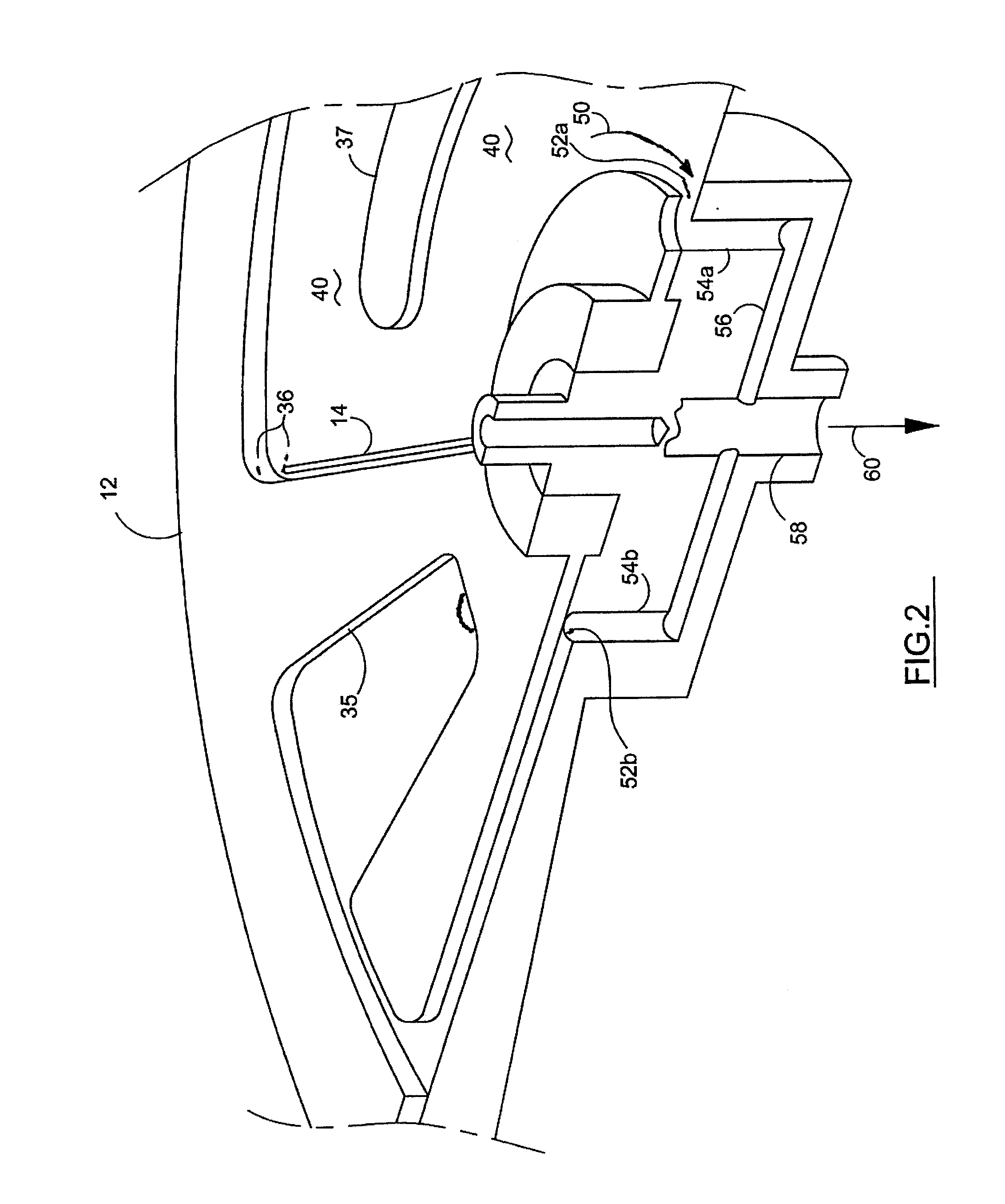
[0049]One embodiment of the present invention includes a flat aluminum disc or back plate 10 (FIG. 1) with two shallow generally radial pockets milled into one side. These milled pockets are sealed into hydraulic passages by the gasket 16 and a polycarbonate cover plate is placed over top of the gasket (not shown). A plurality of capillary tubes (see tube 14) may be disposed or formed on the disc. The disc is secured by an aluminum clamp ring and face washers and through-bolted (see bolt hole 37, FIG. 1) to the aluminum back plate 10. A central brass hub is bolted to the aluminum back plate 10. The brass hub, holding emulsification device 11, is machined to provide a sealed liquid inlet 20 on the front side, and a sealed pressurized gas harvest port 60 (FIG. 2), ...


PUM

PropertyMeasurementUnit
Angleaaaaaaaaaa
Forceaaaaaaaaaa
Flow rateaaaaaaaaaa

Abstract

The gas compression method / system restricts flow of emulsified liquid-gas mixture through many substantially radial capillary tube-passages in a rotating disk by either one-way valves, narrowing the passages, hydraulic impedance and / or reinforcement of coriolis forces in terminal end tail segments of the capillary passages. Compressed gas is released from peripherally collected compressed gas-liquid emulsion (beyond the terminal ends of the tubes) in a arcuate peripheral disc space when the compressed gas bubbles emerge from the peripherally collected emulsion. A compressed gas drain draws off gas from the peripheral space. Liquid drain draws off liquid from the space. In different embodiments, radial outboard flow through the capillaries is effected by various one-way valves which may be a single valve in the passage or multiple valves. Coriolis force in tail segments is enhanced by angular displacement in the direction of rotation. Valves may be used in combination with such tail-end segments.

Description

[0001]This is a regular patent application claiming priority of provisional patent application Ser. No. 62 / 222,261, filed Sep. 23, 2015 and provisional patent application Ser. No. 62 / 063,463, filed Oct. 14, 2014, both of which are currently pending and the contents thereof is incorporated herein by reference thereto.[0002]The present invention relates to a method of compressing gas using flow restriction technology and gas compressors with such technology.CROSS REFERENCED RELATED APPLICATION[0003]The present method of compressing gas and gas compressor is related to pending U.S. patent application Ser. No. 14 / 280,780 filed May 19, 2014, published as U.S. Patent Publication US 2015 / 0023807 on Jan. 22, 2015, entitled Centrifugal Gas Compressor Method and System, the contents of which is incorporated herein by reference thereto.BACKGROUND OF THE INVENTION[0004]Gas compressors are used for many items in the consumer market (to inflate basketballs, toys and tires) and in the industrial m...

Claims


Application Information

Patent Timeline
IPC IPC(8): F04D29/28B01D19/00F04D25/02F04F5/04F04D17/10F04D17/18
CPCF04D29/284F04D17/10B01D19/0057F04D25/02F04F5/04F04D17/18F04D17/167F04D31/00F04F5/06F05D2210/132
Inventor CHERRY, MARK A.ALDERMAN, ROBERT A.SHILLINGER, D. HANS
Owner CARNOT COMPRESSION INC
Learn More