
Method for assessing stenosis severity in a lesion tree through stenosis mapping

a stenosis mapping and lesion technology, applied in the field of accurately identifying and diagnosing coronary artery disease, can solve the problems of significant number of low to mid-risk patients being unnecessarily admitted from emergency rooms to the hospital for further testing, and the heart muscle cannot get the required blood and oxygen it needs. to achieve the effect of accurately assessing complex luminal diameter stenosis

Inactive Publication Date: 2016-04-07
AUTHENTIC
View PDF2 Cites 1 Cited by
  • Summary
  • Abstract
  • Description
  • Claims
  • Application Information

AI Technical Summary

Benefits of technology

This patent describes a way to non-invasively assess the narrowing of blood vessels in a way that allows clinicians to better diagnose and treat pre-clinical stages of cardiovascular disease. The method is less expensive than previous methods and provides more definitive information about the severity of the narrowing.

Problems solved by technology

When this occurs, the heart muscle cannot get the required blood and oxygen it needs, which can lead to chest pain or a heart attack.
However, current diagnostic techniques are often equivocal, which results in a significant number of low to mid risk patients being unnecessarily admitted from emergency rooms to the hospital for further testing.
After further testing, CAD is ruled out for many of these low to mid risk patients, which results in unnecessary costs exceeding $10 billon.
Invasive diagnostic techniques for CAD are known, but they are extremely expensive.
While these non-invasive techniques are less expensive, they have limitations.
However, in cases where intermediate stenosis lesions exist, the specificity and accuracy of this method is lower, despite its high negative prediction value.
One known cause for this low specificity is that the luminal diameter stenosis and luminal area stenosis assessment techniques may lead cardiac surgeons to overestimate CAD severity similar to rates reported by cardiologists and radiologists.
As such, the luminal diameter assessment technique may misrepresent true lumen narrowing in many instances, which does not solve the issue of unnecessary costs associated with accurately assessing the existence of CAD.
FFR measurement, however, is an invasive method where a pressure sensitive angioplasty wire is placed directly into the coronary artery through coronary catheterization.
The FFRct method is complicated as it uses computational modeling on the CCTA for the whole coronary artery tree including a segment of the aorta artery.
The virtual FFR method is similarly complicated as it uses computation modeling on the rotational coronary angiography (RoCA) images for the whole major vessel.
This requires the estimation of sophisticated boundary conditions and initial conditions, which can be difficult to estimate accurately.
In addition, computational modeling requires significant resources (both computational and labor) to segment the whole coronary artery tree domain or the whole vessel domain to construct the patient specific arterial lumen geometry as input to the CFD.
One disadvantage is that CFD simulation needs large computational resources as it is a computational insensitive algorithm.
Another disadvantage is that the large domain requirement limits the number of CCTA scans that may be used due to the localized low image quality on a normal vessel.
Additionally, imaging artifacts such as blurring of motion under limited temporal resolution of imaging, blooming artifacts from calcified plaques under limited spatial resolution of imaging, or even localized noise are more likely to appear in a large domain.
This, in turn, reduces the confidence level of the prediction of CAD by the CFD simulation for FFR value.
This technique, however, has limitations for more complex morphologies of lesions as the accuracy may be affected by the selected flow path despite the fact that the technique has compensated for area difference between the inlet to outlet by using the inlet and outlet radii.

Method used


Image

  • Method for assessing stenosis severity in a lesion tree through stenosis mapping
  • Method for assessing stenosis severity in a lesion tree through stenosis mapping
  • Method for assessing stenosis severity in a lesion tree through stenosis mapping

Examples


Embodiment Construction

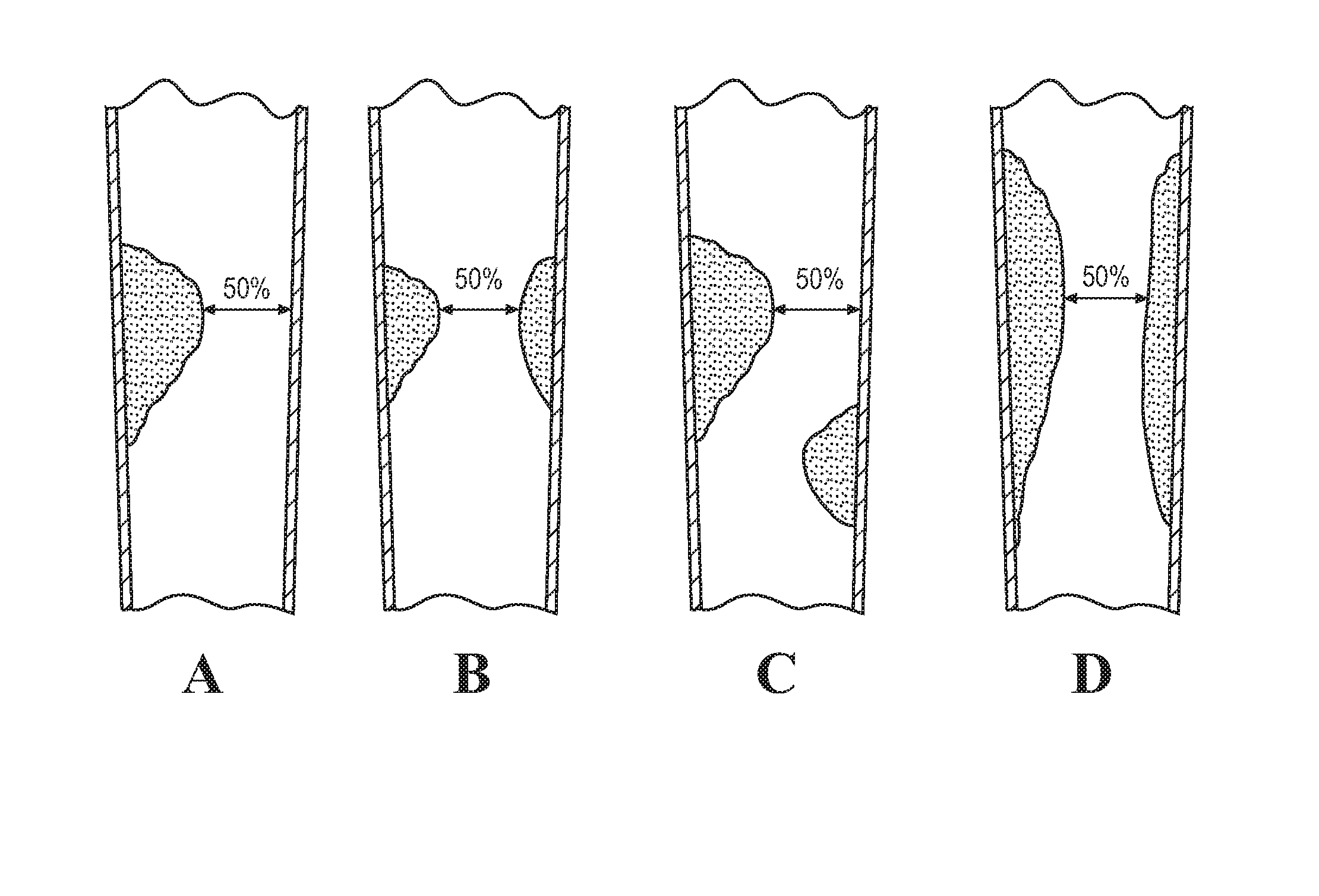
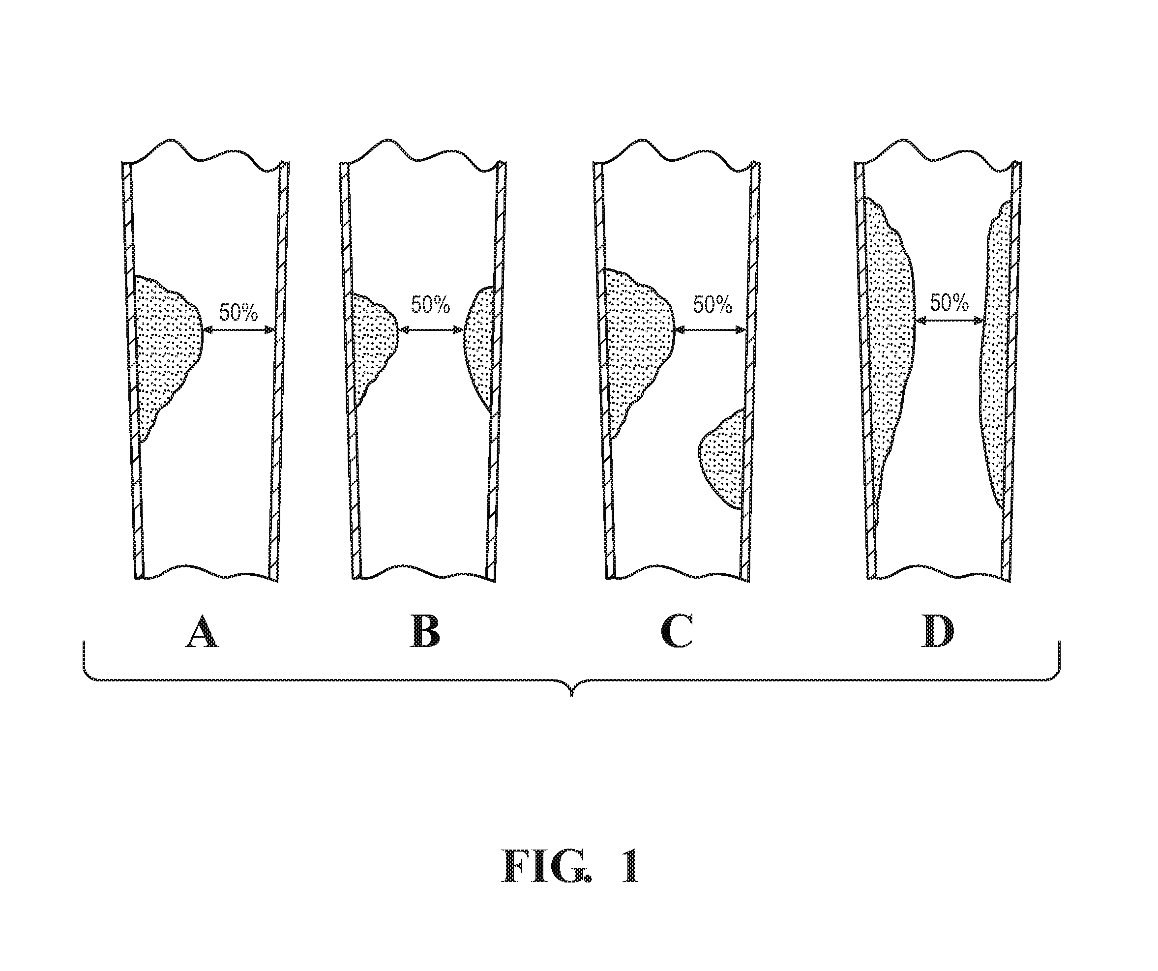
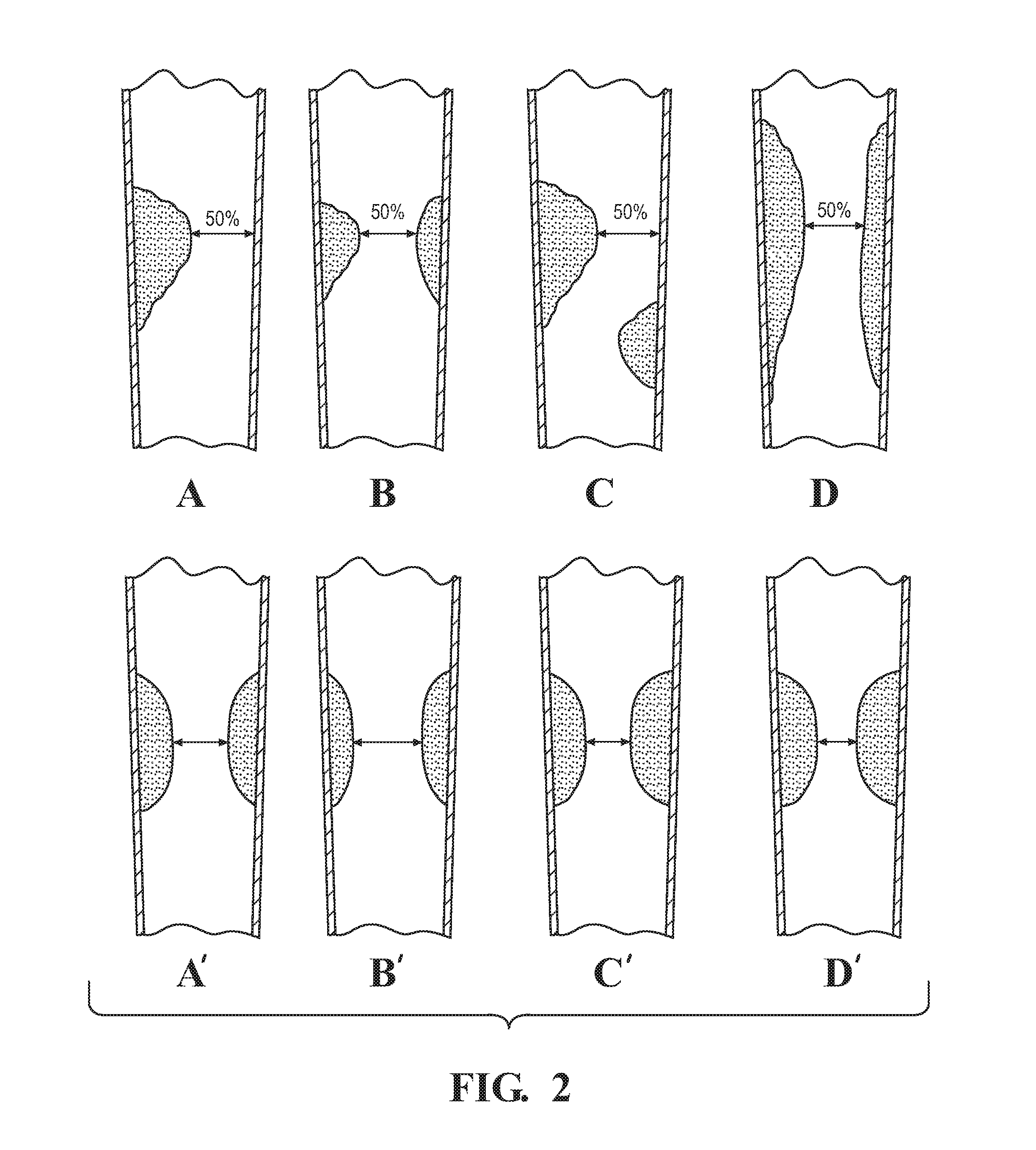
[0034]The present disclosure relates to a method of determining the stenosis severity of an artery, such as a coronary artery, and particularly as it relates to irregular-shaped stenosis or complex morphology of lesions. It will be appreciated, however, that the present disclosure applies to any type of shaped stenosis or any sized stenosis. FIG. 3 schematically illustrates a method 10 in accordance with an aspect of the present disclosure that provides accurate stenosis mapping for complex stenosis in a lesion vessel tree using a computational fluid dynamic (“CFD”) based method in which all outlet branches can be evaluated using a single testing flow with stenosis severity being applied to each outlet branch.

[0035]According to an aspect, relevant data about a patient to be evaluated is initially obtained. The relevant patient data may include patient anatomical data and particularly imaging data of the pertinent areas of concern. The patient anatomical data may be obtained by using...


PUM


Abstract

A method of assessing stenosis severity for a patient includes generating a three dimensional model of a lesion specific vessel tree of the patient. A plurality of inlet and outlet positions are identified in the lesion tree. A total flow rate from the vessel tree model is estimated. A processor and task specific software are utilized to perform computational fluid dynamic simulation on the vessel tree. A flow rate and apparent flow resistance for each of the outlets is then determined. At least one ideal model is generated. A computational fluid dynamic simulation is performed on the at least one ideal model. A level of stenosis severity is determined for each of the outlets.

Description

CROSS-REFERENCE TO RELATED APPLICATIONS[0001]The present application claims priority to U.S. Provisional Patent Application Ser. No. 62 / 205,466, filed Aug. 14, 2015 and entitled “System and Method for Assessing Stenosis Severity Through Stenosis Mapping” and is also a continuation-in-part of U.S. patent application Ser. No. 14 / 643,024, filed Mar. 10, 2015 and entitled “Method for Assessing Stenosis Severity Through Stenosis Mapping”, which is a continuation of U.S. Pat. No. 8,831,315, filed Dec. 5, 2013 and entitled “Method for Assessing Stenosis Severity Through Stenosis Mapping”, the disclosures of which are all hereby incorporated by reference as though set forth fully herein.TECHNICAL FIELD[0002]The present disclosure broadly relates to a method of accurately identifying and diagnosing coronary artery disease. More specifically, the present disclosure relates to a noninvasive method of accurately identifying and diagnosing coronary artery disease as it relates to lesions of comp...

Claims


Application Information

Patent Timeline
IPC IPC(8): G06F19/00
CPCG06F19/3437G06T7/0014A61B5/0044A61B5/02007A61B5/02035A61B5/021A61B5/0263A61B5/1075A61B5/7278A61B5/7282A61B6/504A61B8/0891A61B2576/00A61B2576/023G06T2207/10101G06T2207/10132G06T2207/30048G06T2207/30104G16H50/50
Inventor WU, ZHONGLECHERNETT, JOREY
Owner AUTHENTIC
Learn More