
Apparatus and method for measuring velocity and composition of material in and adjacent to a borehole

a technology of apparatus and method, applied in the field of flow measurement, can solve the problem of increasing the noise in the measurement signal

Active Publication Date: 2016-04-07
WOLLIN VENTURES
View PDF6 Cites 0 Cited by
  • Summary
  • Abstract
  • Description
  • Claims
  • Application Information

AI Technical Summary

Benefits of technology

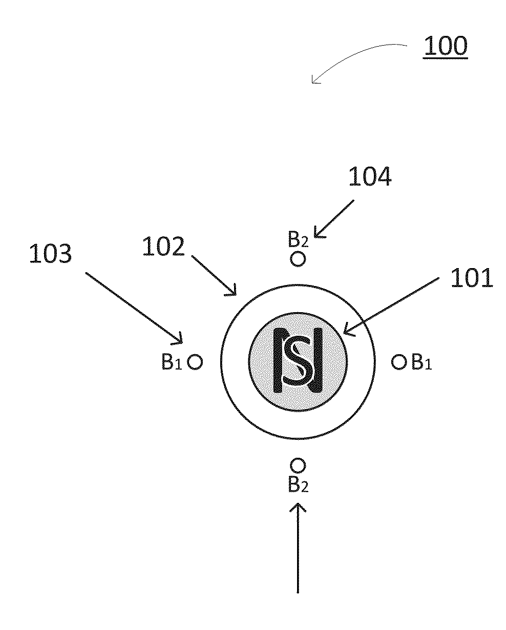
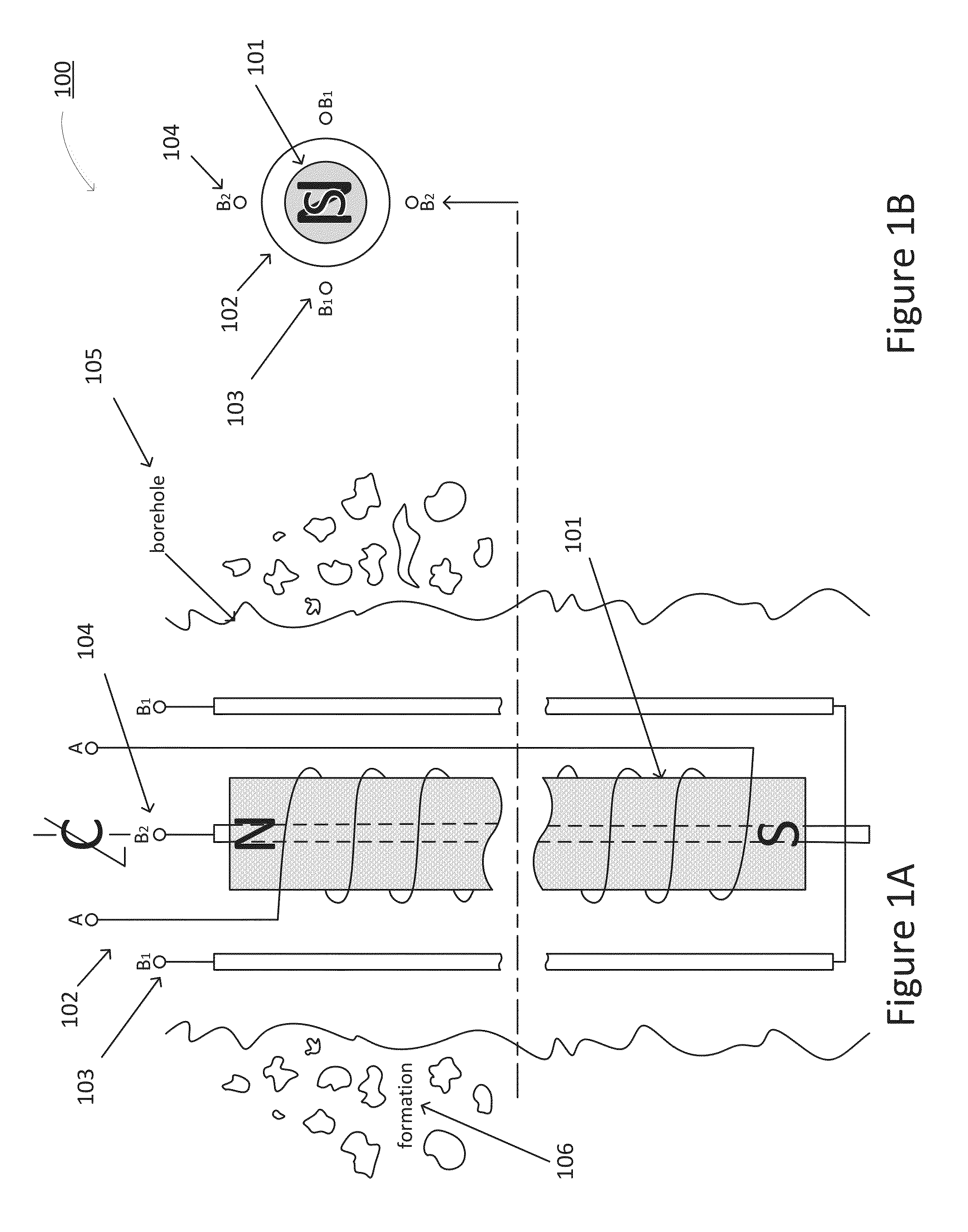
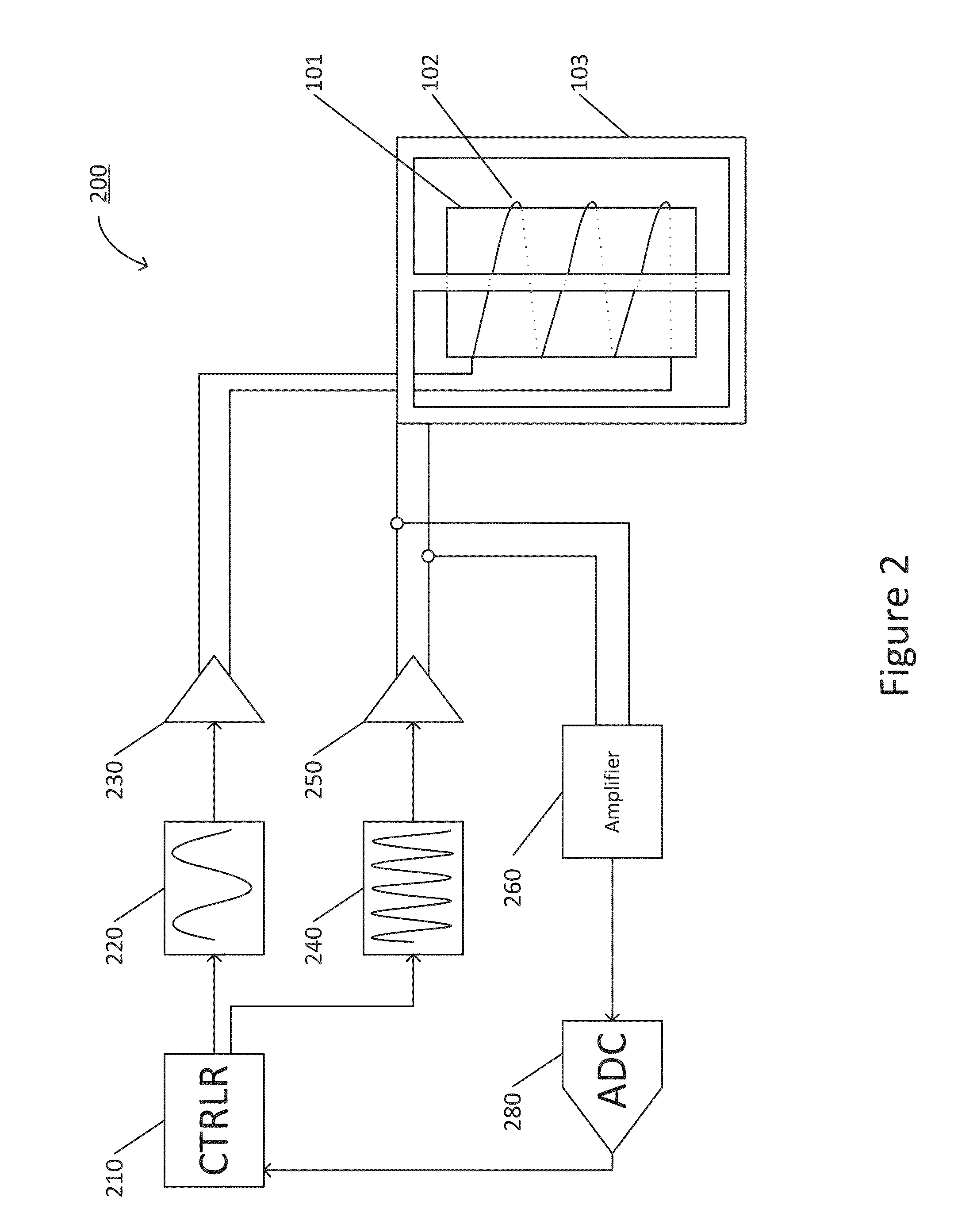
This patent describes a flow measurement device for measuring flow in a borehole of an earth formation. The device includes a magnet, an electromagnet, and an RF coil. The magnet generates a static solenoidal magnetic field with decreasing strength peripherally. The electromagnet generates a time varying solenoidal magnetic field. The RF coil generates an RF magnetic field that rotates at a Larmor radio frequency corresponding to the static solenoidal magnetic field. The device measures the flow velocity through the region of interest around the device by analyzing the received signal induced by the magnetic field. The method includes inserting the device into the borehole and adjusting the current to maximize the received signal. The device and method provide a reliable and accurate way to measure flow in a borehole.

Problems solved by technology

Those prior art methods employ pulse techniques that broaden the bandwidth thereby increasing the noise in the measurement signal.
Further, prior art methods pertain to measurements within a conduit and not to measurements around the device where there may be a strong component of velocity peripheral to the device.

Method used


Image

  • Apparatus and method for measuring velocity and composition of material in and adjacent to a borehole
  • Apparatus and method for measuring velocity and composition of material in and adjacent to a borehole
  • Apparatus and method for measuring velocity and composition of material in and adjacent to a borehole

Examples


Embodiment Construction

[0018]The following description is directed to certain implementations for the purposes of describing the innovative aspects of this disclosure. However, a person having ordinary skill in the art will readily recognize that the teachings herein can be applied in a multitude of different ways. The described implementations may be implemented in any device, apparatus, or system that is capable of measuring velocity of flow in and around a borehole in an earth formation.

[0019]The following disclosure pertains to measuring velocity of flow and composition of material moving within a borehole or peripherally in a surrounding volume. The borehole may be present in an earth formation or a man-made structure. The borehole may contain a flow measurement device employing nuclear spin or electron spin magnetic resonance for measurement. Applications of the measurement device disclosed herein include hydrocarbon production, hydraulic fracturing, groundwater migration, contaminant diffusion, wir...


PUM


Abstract

This disclosure provides systems, methods, and apparatus for measuring flow in and around a borehole of an earth formation. A flow measurement device can include a magnet configured to generate a static solenoidal magnetic field with a field intensity that decreases in strength peripherally from the magnet, an electromagnet disposed around the magnet and configured to generate a time varying solenoidal magnetic field, and a radio frequency (RF) coil disposed around the magnet and configured to generate an RF magnetic field transverse to the static solenoidal magnetic field. The flow measurement device can calculate a flow velocity in and around the flow measurement device based upon a signal received by the RF coil.

Description

RELATED APPLICATIONS[0001]This application claims benefit under 35 U.S.C. §119(e) of Provisional Application Ser. No. 62 / 060,321, filed Oct. 6, 2014, entitled “Apparatus and Method for Measuring Velocity and Composition of Material in and Adjacent to a Borehole.”BACKGROUND OF THE INVENTION[0002]1. Field of the Invention[0003]This disclosure relates to the field of flow measurement, and in particular to apparatus and processes for measuring flow using nuclear or electron magnetic resonance.[0004]2. Description of the Prior Art[0005]The idea of studying flow by magnetic resonance dates back to the work of the early pioneers as described, for example, in Mansfield, P; Morris, P. G.; “NMR Imaging in Biomedicine”; Advances in Magnetic Resonance, Supplement 2; 1982; Academic Press, Inc. Orlando 32887; p. 235 section 7.3.5. Prior art devices for flow measurement or flow mapping rely on two well-known methods viz. “Time-of-Flight” of saturated or unsaturated spins or “Phase-Encoding” by app...

Claims


Application Information

Patent Timeline
IPC IPC(8): G01F1/716E21B47/10G01R33/34
CPCG01F1/716E21B47/10G01R33/34053G01R33/34076G01N24/081G01R33/3808G01R33/381G01R33/383G01R33/4835
Inventor WOLLIN, ERNEST
Owner WOLLIN VENTURES
Learn More