
Zoom lens

a zoom lens and zoom technology, applied in the field of zoom lenses, can solve the problems of small zoom lens size, large power of each lens group, difficult to correct aberration, etc., and achieve the effect of easy zooming of the zoom lens, high performance, and decreasing the telephoto ratio

Inactive Publication Date: 2016-03-31
CBC
View PDF1 Cites 3 Cited by
  • Summary
  • Abstract
  • Description
  • Claims
  • Application Information

AI Technical Summary

Benefits of technology

The present invention provides a zoom lens that has a high optical performance in the entire zoom range at a high zoom ratio and also has a shorter total optical length compared to conventional zoom lenses. The lens system includes a first lens group with a positive refractive power and a focusing function, a second lens group with a negative refractive power and a variator function of performing zooming, a third lens group with a positive refractive power and a diaphragm, and a fourth lens group with a positive or negative refractive power. The first lens group is moved along the optical axis during zooming, while the fourth lens group is moved along the optical axis and compensates for position of the imaging plane at the telephoto end. The lens system also includes at least one concave lens and conditional formulas to achieve the desired optical performance.

Problems solved by technology

Further, since sizes of a housing for housing a lens and a camera platform are restricted, it is also required to miniaturize the zoom lens.
However, when a total optical length of the zoom lens is set to be short, the power of each lens group becomes large, thus possibly making it difficult to correct the aberration.
Thus, it would be difficult to achieve both of obtaining a high optical performance in the entire zoom range at a high zoom ratio, and shortening the total optical length of the zoom lens.

Method used


Image

  • Zoom lens
  • Zoom lens
  • Zoom lens

Examples


example 1

[0114]Example 1 will be described using FIG. 1 to FIG. 5.

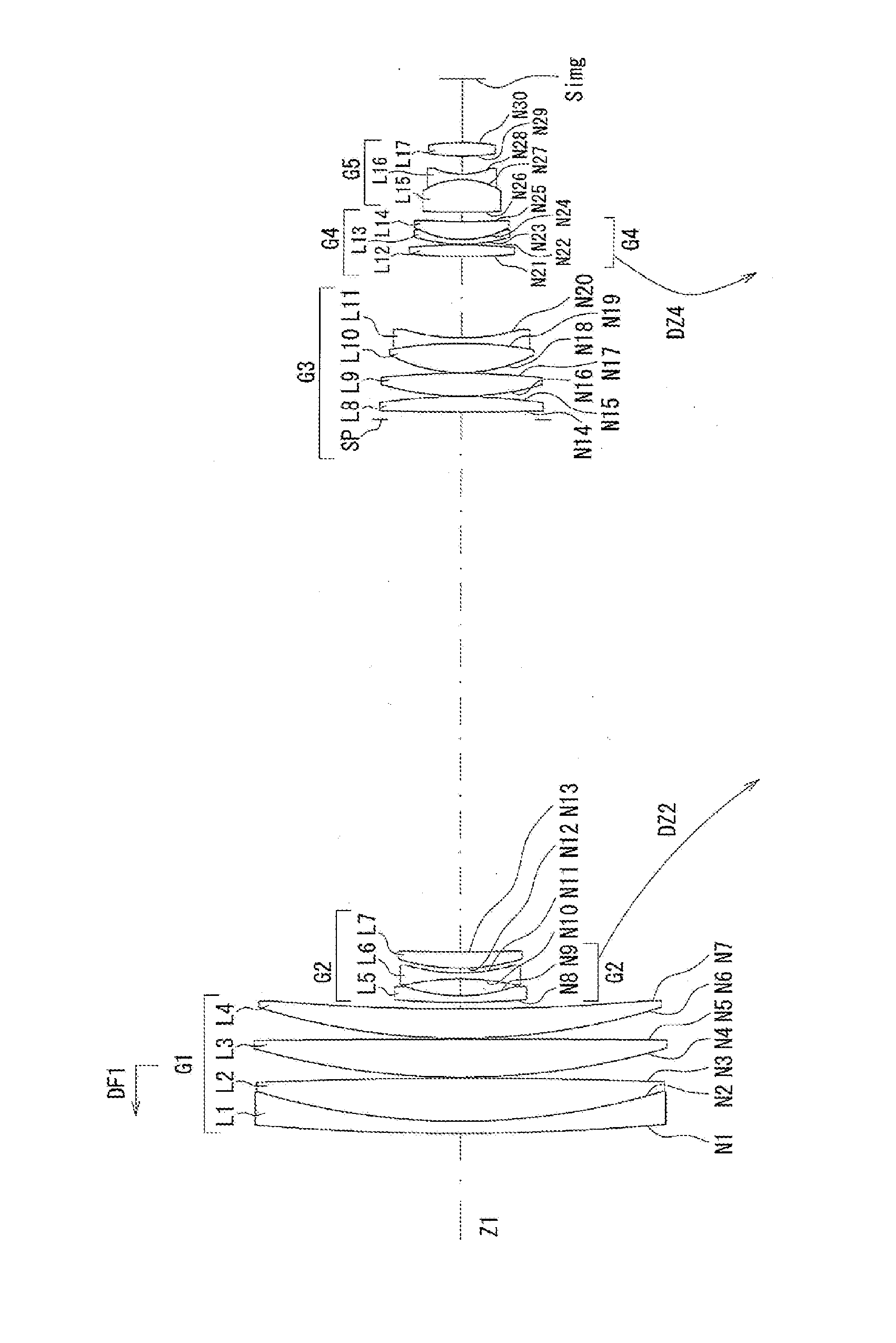
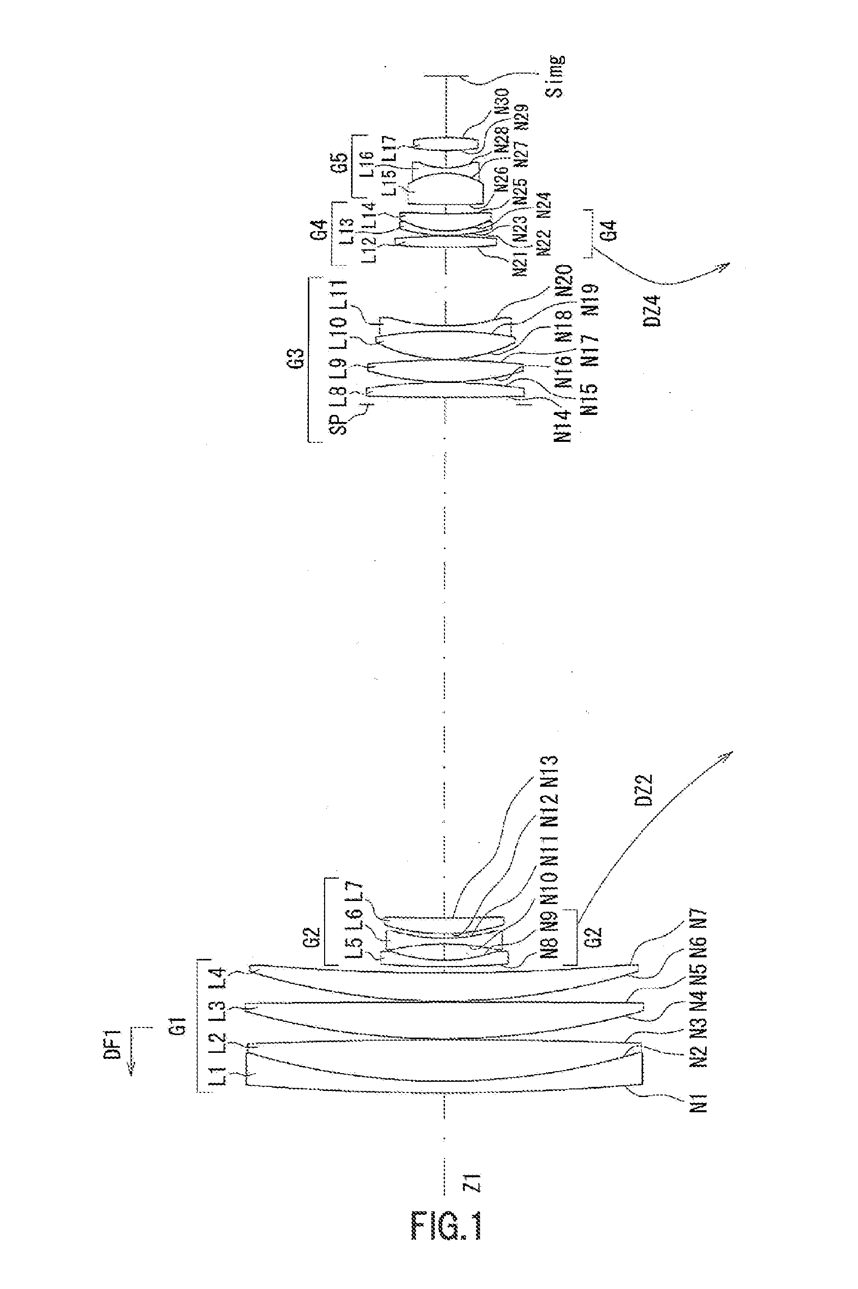
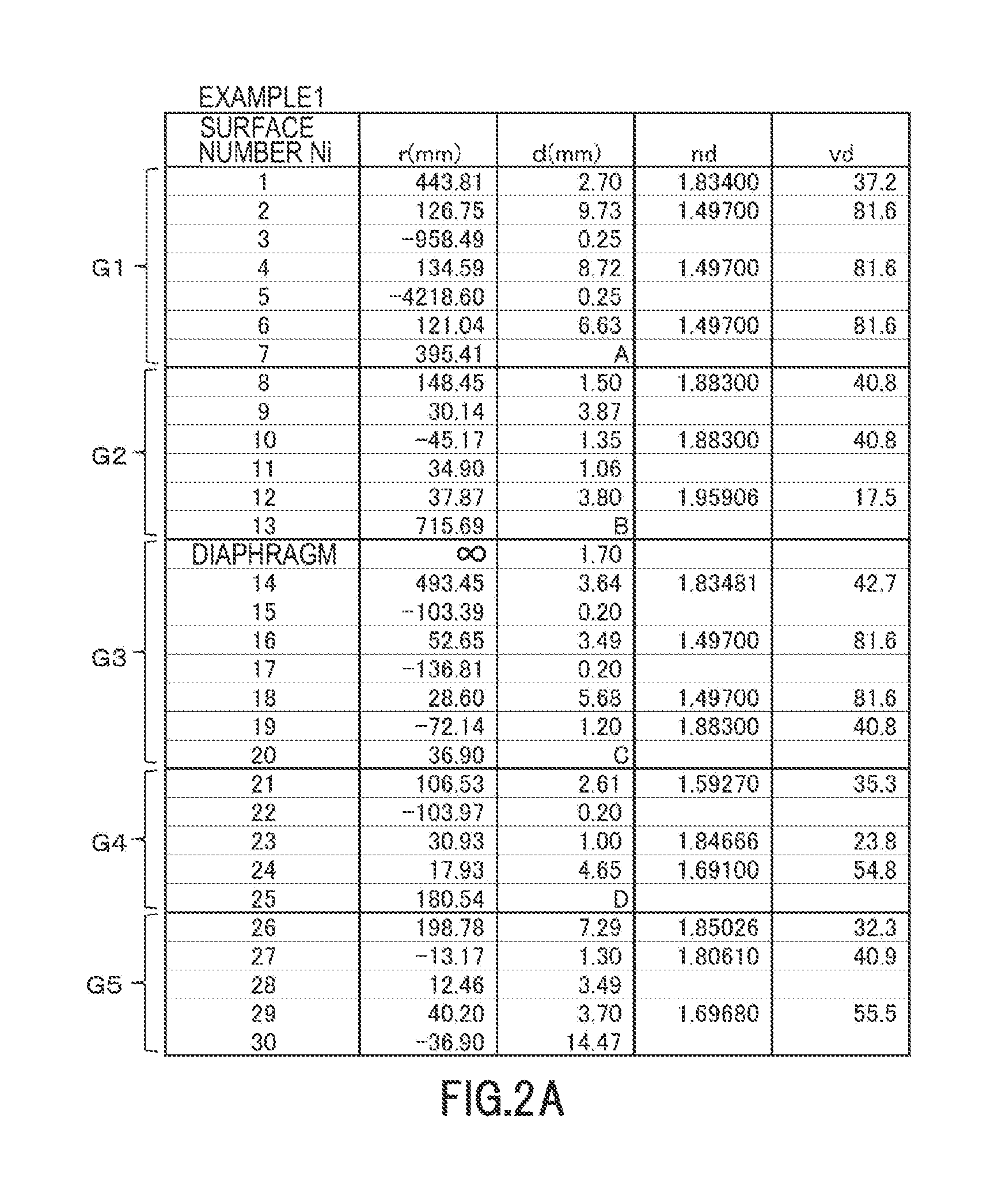
[0115]FIG. 1 is a cross-sectional view showing the configuration of the zoom lens of example 1 at a wide angle end. FIG. 2A is a view showing parameters of each lens group of the zoom lens of example 1, FIG. 2B is a view showing each parameter of the zoom lens of example 1 at a wide angle end, in an intermediate area, and at a telephoto end, FIG. 2C is a view showing the value of each conditional formula of the zoom lens of example 1, FIG. 3A to FIG. 3C are longitudinal aberration diagrams at the wide angle end of the zoom lens of example 1, wherein FIG. 3A is a spherical aberration diagram, FIG. 3B is an astigmatism diagram and astigmatic field curves diagram, FIG. 3C is a distortion diagram, and FIG. 3D to FIG. 3G are lateral aberration diagrams at the wide angle end of the zoom lens of example 1, FIG. 3D is a lateral aberration diagram in a meridional (tangential) direction at a half angle of view of 24.19°, FIG. 3E is a la...

example 2

[0125]Example 2 will be described, using FIG. 6 to FIG. 10. Configurations of FIG. 6 to FIG. 10 are similar to the configurations of FIG. 1 to FIG. 5 of example 1.

[0126]As shown in FIG. 6, the zoom lens of example 2 has the following configuration.

[0127]The first lens group G1 consists of a cemented lens composed of an object side convex negative meniscus lens L1 and a double-sided positive lens L2, and an object side convex positive meniscus lens L3, sequentially from the object side.

[0128]The second lens group G2 consists of a double-sided concave negative lens L4, a double-sided concave negative lens L5, and an object side convex positive meniscus lens L6, sequentially from the object side.

[0129]The third lens group G3 includes a diaphragm SP, a double-sided convex positive lens L7, a double-sided convex positive lens L8, and a cemented lens composed of a double-sided convex positive lens L9 and a double-sided concave negative lens L10, sequentially from the object side.

[0130]The...

example 3

[0136]Example 3 will be described, using FIG. 11 to FIG. 15. The configurations of FIG. 11 to FIG. 15 are similar to the configurations of FIG. 1 to FIG. 5 of example 1. It should be noted that the line types for the wavelength of the light in the spherical aberration diagram of (a) and the lateral aberration diagrams of (d) to (g) in each of FIG. 23 to FIG. 25, are different from the line types in each of FIG. 3 to FIG. 5.

[0137]As shown in FIG. 11, the zoom lens of example 3 has the following configuration.

[0138]The first lens group G1 consists of a cemented lens composed of an object side convex negative meniscus lens L1 and a double-sided convex positive lens L2, and an object side convex positive meniscus lens L3, sequentially from the object side.

[0139]The second lens group G2 consists of an object side convex negative meniscus lens L4, a double-sided concave negative lens L5, and an object side convex positive meniscus lens L6, sequentially from the object side.

[0140]The third...


PUM


Abstract

There is provided a zoom lens, consisting of sequentially from an object side: a first lens group having a positive refractive power and a focusing function; a second lens group having a negative refractive power and having a variator function of performing zooming; a third lens group having a positive refractive power and a diaphragm; a fourth lens group having a positive refractive power, and having a compensator function of correcting a position of an imaging plane at the time of zooming; and a fifth lens group having a positive or negative refractive power, wherein the second lens group is moved to the imaging plane side from the object side along an optical axis, and the fourth lens group is moved along the optical axis in a state of fixing the first lens group, the third lens group, and the fifth lens group at the time of zooming from a wide angle end to a telephoto end, and only the first lens group is moved along the optical axis at the time of focusing.

Description

CROSS-REFERENCE TO RELATED APPLICATIONS[0001]This Application is a U.S. National Phase Application under 35 U.S.C. 371 of International Application No. PCT / JP2013 / 065495, filed Jun. 4, 2013 and published in Japanese as WO 2014 / 196022 A1 on Dec. 11, 2014. The entire disclosure of the above application is incorporated herein by reference.BACKGROUND[0002]1. Technical Field[0003]The present invention relates to a zoom lens.[0004]2. Description of Related Art[0005]A zoom lens consisting of a plurality of lens groups as a high power zoom, is known. Japanese Patent Laid Open Publication No. 2008-241884 or Japanese Patent Laid Open Publication No. 2006-39005 discloses a zoom lens consisting of a first lens group having a positive refractive power, a second lens group having a negative refractive power, a third lens group having a positive or negative refractive power, and a fourth lens group having a positive refractive power and a diaphragm.[0006]In recent years, with a miniaturization of ...

Claims


Application Information

Patent Timeline
Patent Type & Authority Applications(United States)
IPC IPC(8): G02B13/00G02B15/173G02B27/00
CPCG02B13/009G02B27/0025G02B15/173G02B15/145113G02B15/145129
Inventor HIRANO, KATSUYA
Owner CBC
Learn More