
Electrical Connector with Optical Channel

a technology of optical channels and electrical connectors, applied in the direction of optical elements, coupling device connections, instruments, etc., can solve the problems of increasing the overall volume of standardized connectors, affecting the affecting the overall performance of electrical connectors, so as to reduce the number of components, reduce the cost of components, and add significant cost to the connector

Inactive Publication Date: 2016-03-31
LATTICE SEMICON CORP
View PDF0 Cites 13 Cited by
  • Summary
  • Abstract
  • Description
  • Claims
  • Application Information

AI Technical Summary

Benefits of technology

The patent describes how the optical transport structure can be designed in different ways, using optically transparent materials or as a hollow waveguide. The structure is preferably designed to not add significant cost to the connector and can be made using a variety of methods like molding, deposition, etching, printing, or stamping. The shape of the structure can be arbitrary. The most suitable characteristics for the connector can be chosen based on performance and cost. The technical effects of this patent are the ability to design an optical transport structure that is cost-effective and suitable for various connector applications.

Problems solved by technology

There is also significant price pressure on electrical connectors.
The use of standardized connectors also increases the overall volume for the standardized connector, which results in lower prices.
However, electrical connectors use electrical conductors to transmit data and electrical conductors are limited in data rate, particularly in light of the increasing demand for bandwidth driven by video and other data-intensive applications.

Method used


Image

  • Electrical Connector with Optical Channel
  • Electrical Connector with Optical Channel
  • Electrical Connector with Optical Channel

Examples


Embodiment Construction

[0023]The Figures (FIG.) and the following description relate to various embodiments by way of illustration only. It should be noted that from the following discussion, alternative embodiments of the structures and methods disclosed herein will be readily recognized as viable alternatives that may be employed without departing from the principles discussed herein. Reference will now be made in detail to several embodiments, examples of which are illustrated in the accompanying figures. It is noted that wherever practicable similar or like reference numbers may be used in the figures and may indicate similar or like functionality.

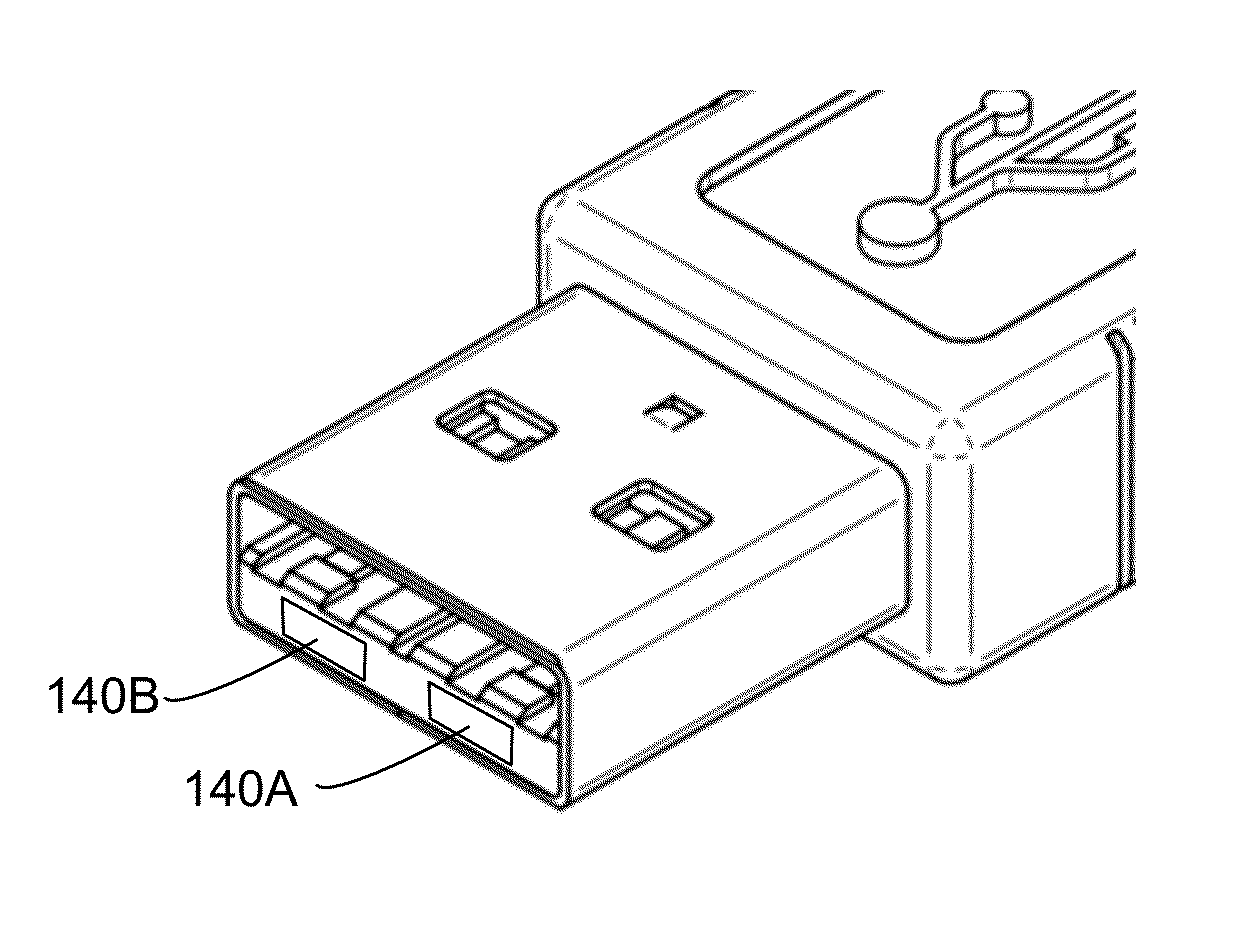
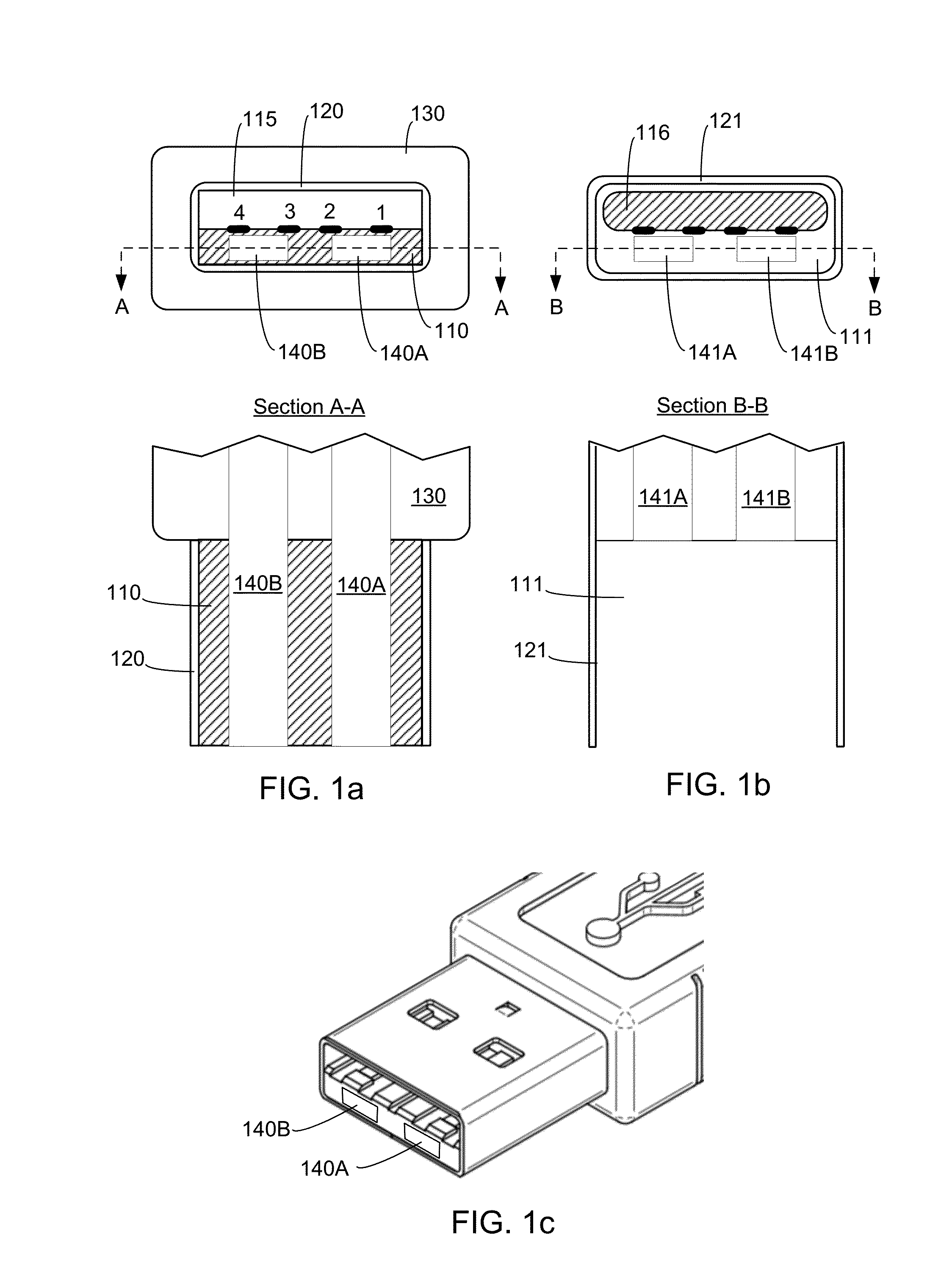
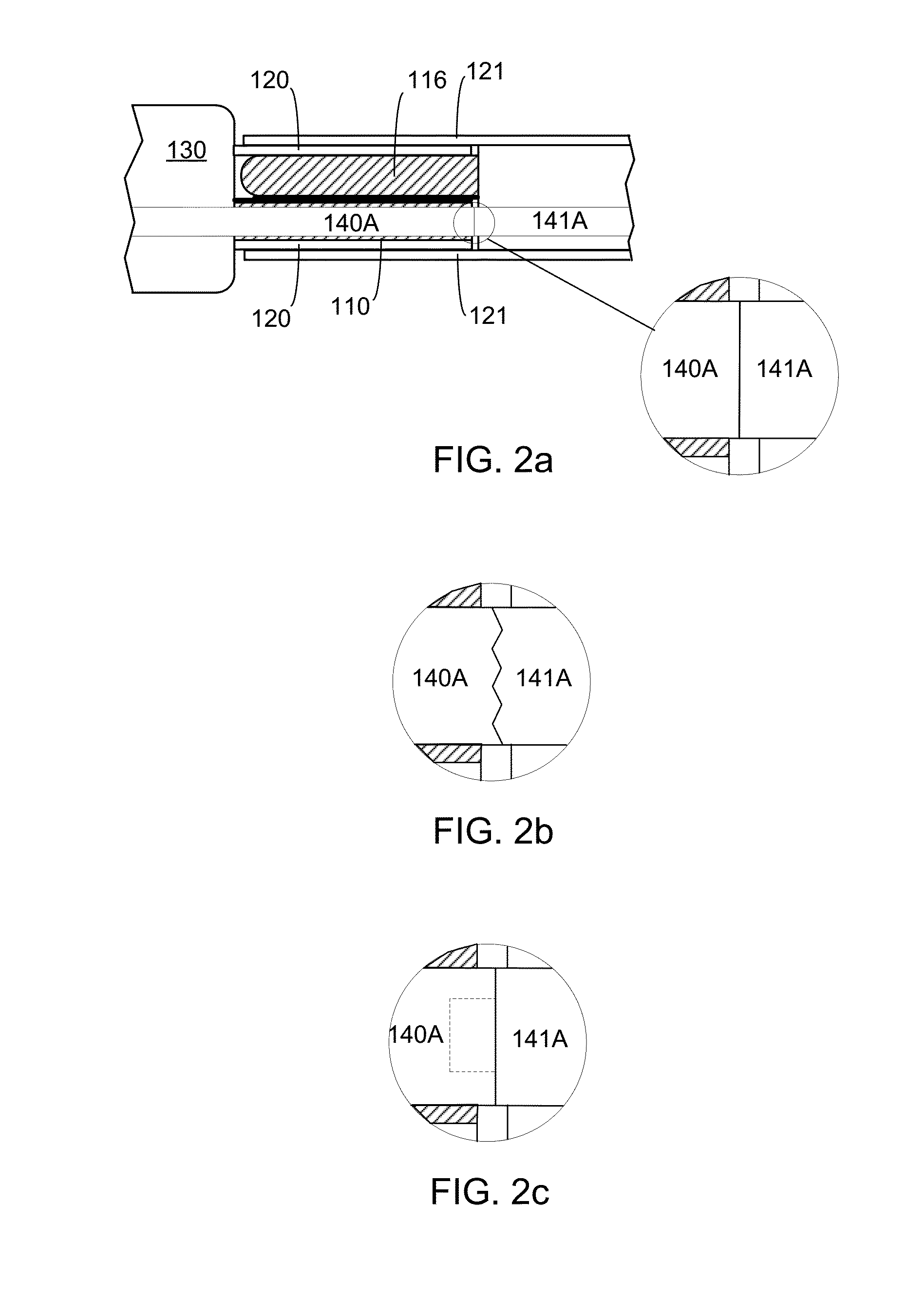
[0024]FIGS. 1a-b are diagrams of hybridized USB Type A connectors. USB connectors come in mating pairs, with one connector referred to as a plug and the other as the receptacle. The plug typically connects to a cable (i.e., is cable-facing), and the receptacle typically connects to a device (i.e., is device-facing). Connector pairs may also be referred to as...


PUM


Abstract

A hybridized connector is based on an existing standard for an electrical connector but also provides an optical channel for increased data rate.

Description

BACKGROUND[0001]1. Field of the Disclosure[0002]This disclosure pertains in general to connectors for data communications.[0003]2. Description of the Related Art[0004]Electrical connectors are an important component for the compute and networking ecosystem. There is a large installed base and continuing strong demand for electrical connectors. There is also significant price pressure on electrical connectors. Most electrical connectors are specified by standards to insure interoperability. The use of standardized connectors also increases the overall volume for the standardized connector, which results in lower prices. However, electrical connectors use electrical conductors to transmit data and electrical conductors are limited in data rate, particularly in light of the increasing demand for bandwidth driven by video and other data-intensive applications.[0005]Therefore, there is a need for improved connectors.SUMMARY[0006]Embodiments of the present disclosure are related to connec...

Claims


Application Information

Patent Timeline
Patent Type & Authority Applications(United States)
IPC IPC(8): G02B6/38H01R13/658H01R24/64
CPCG02B6/3817H01R13/658H01R24/64
Inventor BULLOCK, NEILKIM, KIHONGCHOI, JOOHONG
Owner LATTICE SEMICON CORP
Learn More