Vehicle grill shutter, vehicle flap member, and actuator
a technology for vehicle flaps and actuators, which is applied in the direction of roofs, transportation and packaging, vehicle arrangements, etc., can solve the problems of affecting the performance of the vehicle flap, the shaft portion vibrates, and the improvement of sufficient fuel consumption performance cannot be achieved, so as to prevent the vibration of the shaft portion, and prevent the effect of erroneous assembly of the flap member
- Summary
- Abstract
- Description
- Claims
- Application Information
AI Technical Summary
Benefits of technology
Problems solved by technology
Method used
Image

Examples
first embodiment
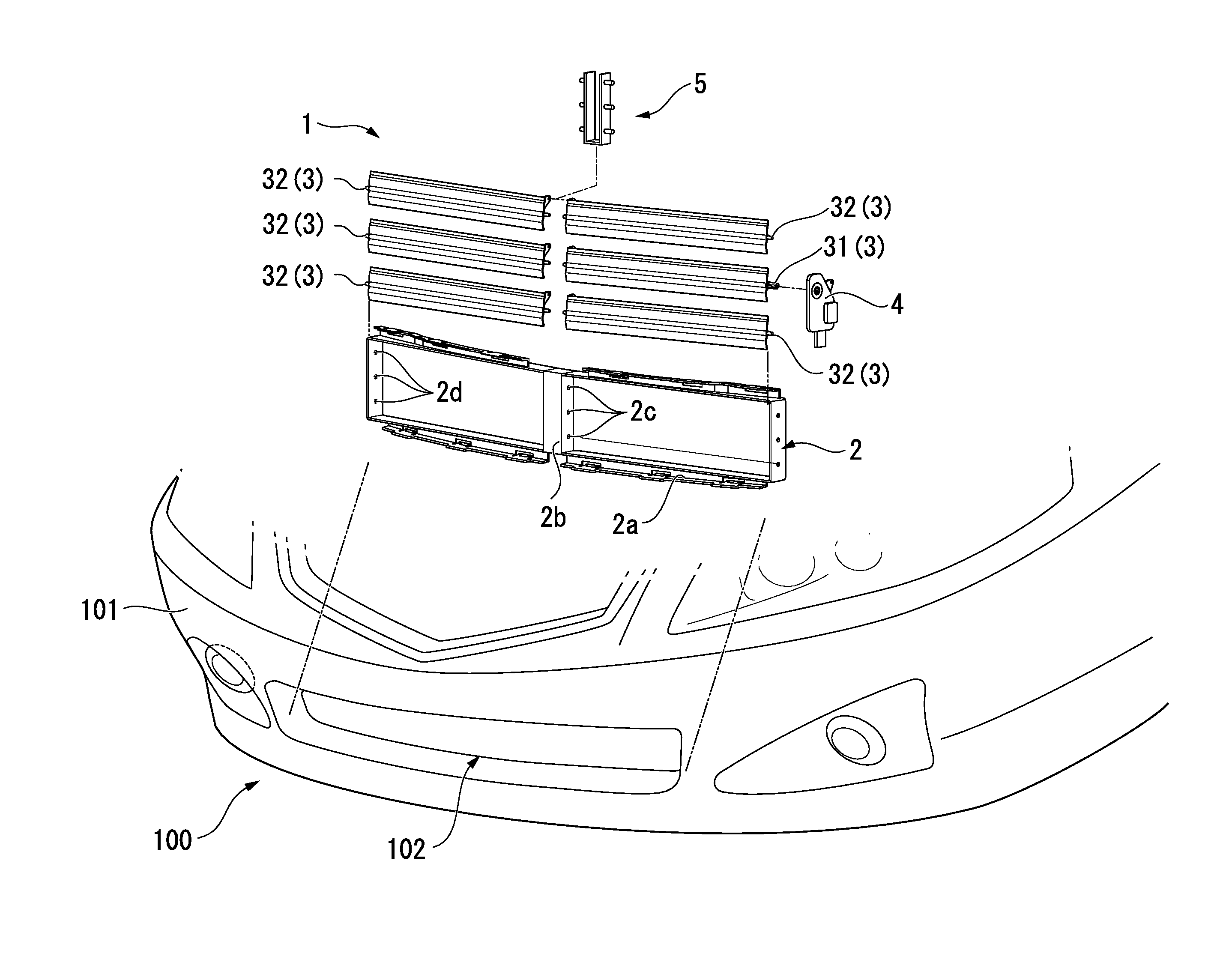
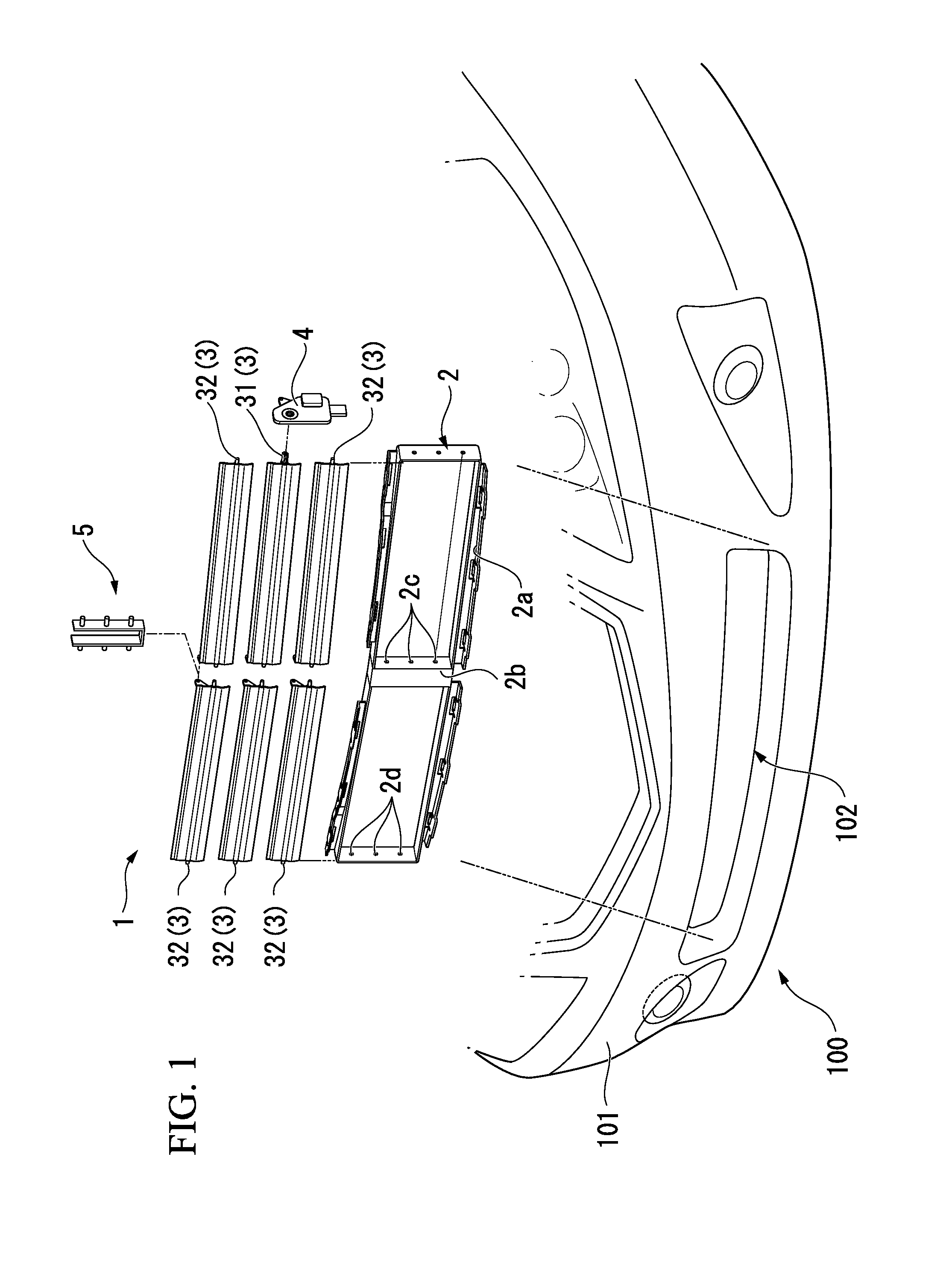
[0041]FIG. 1 is an exploded perspective view of a vehicle grill shutter 1 in a first embodiment of the present invention and is a perspective view showing a front portion of a vehicle. As shown in FIG. 1, a front bumper 101 is provided on a front surface of a vehicle 100 along a vehicle width direction. A grill opening 102 communicating with an engine room is formed on the lower portion side of the front bumper 101. As shown in FIG. 1, a vehicle grill shutter 1 is fixed to a vehicle body so as to be disposed inside the grill opening 102.
[0042]As shown in FIG. 1, the vehicle grill shutter 1 includes a frame 2, flap members 3, an actuator 4, and a link member 5. The frame 2 includes an outer edge portion 2a which is formed in an approximately rectangular shape when viewed from the front surface of the vehicle 100, and a support column 2b which vertically extends from the center of the outer edge portion 2a and is attached to the outer edge portion 2a. In the frame 2, a region surround...
second embodiment
[0069]Next, a second embodiment of the present invention will be described. In addition, in descriptions of the present embodiment, descriptions with respect to the portions similar to those of the first embodiment are omitted or simplified.
[0070]FIG. 7 is a side view when the drive flap member 31 included in a vehicle grill shutter in the present embodiment is viewed from the attachment direction of the shaft portion 31f. In the first embodiment, the notch portion 11 is provided so as to be positioned immediately below when the drive flap member 31 is positioned at the closed position. However, as shown in FIG. 7, in the present embodiment, the notch portion 11 is provided at the position horizontally separated from the center of the shaft portion 31f.
[0071]When the drive flap member 31 is positioned at the closed position, the drive flap member 31 receives the highest wind pressure from the front side (left side in FIG. 7) in the vehicle toward the rear side (right side in FIG. 7...
third embodiment
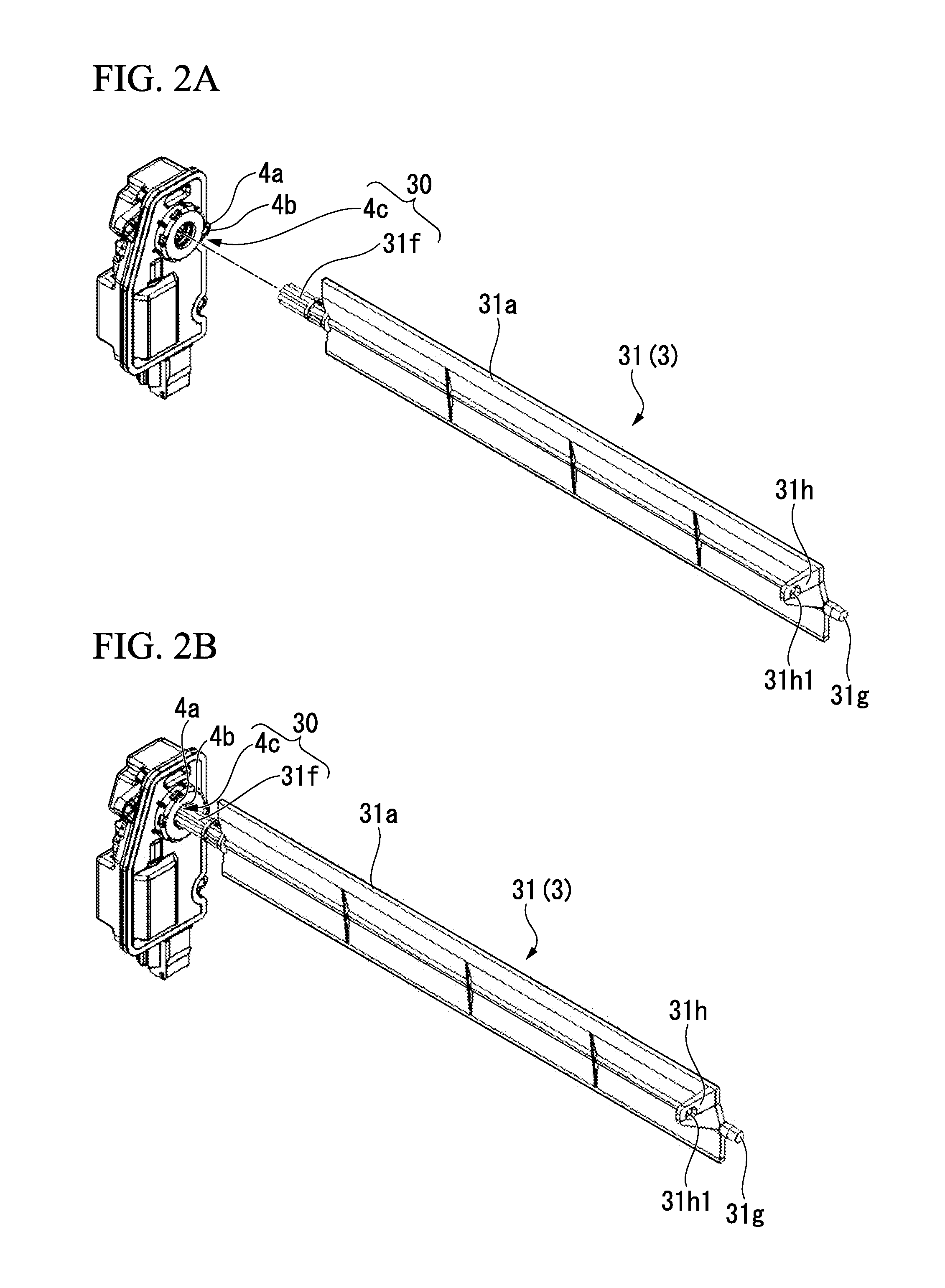
[0072]Subsequently, a third embodiment of the present invention will be described with reference to FIGS. 2 and 8 to 11. In addition, in the descriptions of the present embodiment, descriptions with respect to the portions similar to those of the first embodiment are omitted or simplified.
[0073]FIG. 8 is an enlarged perspective view of the shaft portion 31f included in the drive flap member 31.
[0074]As shown in FIG. 8, the drive flap member 31 according to the present embodiment includes vibration preventing ribs 31i (interposing portions).
[0075]As shown in FIG. 8, each of the vibration preventing ribs 31i is a protrusion which is provided integrally with the teeth 10 of the shaft portion 31f which has the plurality of teeth 10 in the circumferential direction and is formed in a gear shape. In addition, the protrusion protrudes from the surface of the tooth 10 toward the outside in the radial direction. As shown in FIG. 8, the section of each of the vibration preventing ribs 31i is ...
PUM
 Abstract
Description
Claims
Application Information
 - R&D
- Intellectual Property
- Life Sciences
- Materials
- Tech Scout
- Unparalleled Data Quality
- Higher Quality Content
- 60% Fewer Hallucinations
Browse by: Latest US Patents, China's latest patents, Technical Efficacy Thesaurus, Application Domain, Technology Topic, Popular Technical Reports.
© 2025 PatSnap. All rights reserved.Legal|Privacy policy|Modern Slavery Act Transparency Statement|Sitemap|About US| Contact US: help@patsnap.com