
Multi-function floating solar power generating system

Inactive Publication Date: 2016-03-24
INST OF NUCLER ENERGY RES ATOMIC ENERGY COUNCIL EXECUTIVE YUAN R O C
View PDF4 Cites 29 Cited by
  • Summary
  • Abstract
  • Description
  • Claims
  • Application Information

AI Technical Summary

Benefits of technology

The present invention provides a multi-function floating solar power generating system that uses massive buoys to form multiple buoy sets for arrangement. This structure makes it stable and easy to expand or reduce the system area for repair and maintenance. Additionally, the system can float on a fluid, solving the problem of land demand for solar power generating systems. This reduces the evaporation rate of the fluid, benefiting reservoirs and catch basins.

Problems solved by technology

Due to the continuous increase in population, the future supply of land will be tight and costly.
The demand in land also threatens the environmental quality of human residences and the production conditions of food.
Although solar power generation is a renewable energy resource having the greatest potential, there are many challenges for floating solar power generation.
Nonetheless, there are still technical challenges to achieve a win-win situation by fully utilizing the local environment and water resources as well as improving the efficiency of solar plants and the quality of water.
Because the solar panels are faced directly toward the sun, the power generating efficiency is worse in the mornings and evenings.
This method has the shadowing problem at the connections of solar panels and affecting the power generating efficiency directly.
Even for photovoltaic tracking and concentrating floating solar systems, complicated mechanical mechanisms induce problems.
Long-term placement on water surfaces results in rust and thus requires frequent maintenance and repair.
Consequently, the power generating efficiency is affected.
All current commercial floating solar power generating systems do not take advantages of the water environment but simply use the water surface for installing the solar systems.
This method complicates the mechanisms and adds weight to the system.
Even when the overall system adopts a photovoltaic tracking system, the complicated mechanical tracking is disadvantageous to long-term placement on water and results in a high failure rate.
None of the above methods can make good use of sunlight resources for the whole day.
In addition, the properties and advantages of water surfaces are not utilized well.

Method used


Image

  • Multi-function floating solar power generating system
  • Multi-function floating solar power generating system
  • Multi-function floating solar power generating system

Examples


Embodiment Construction

[0018]In order to make the structure and characteristics as well as the effectiveness of the present invention to be further understood and recognized, the detailed description of the present invention is provided as follows along with embodiments and accompanying figures.

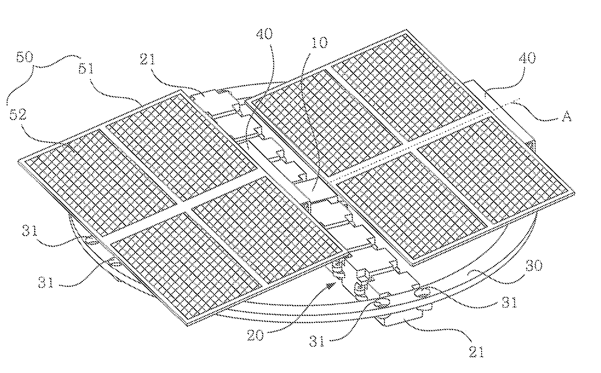
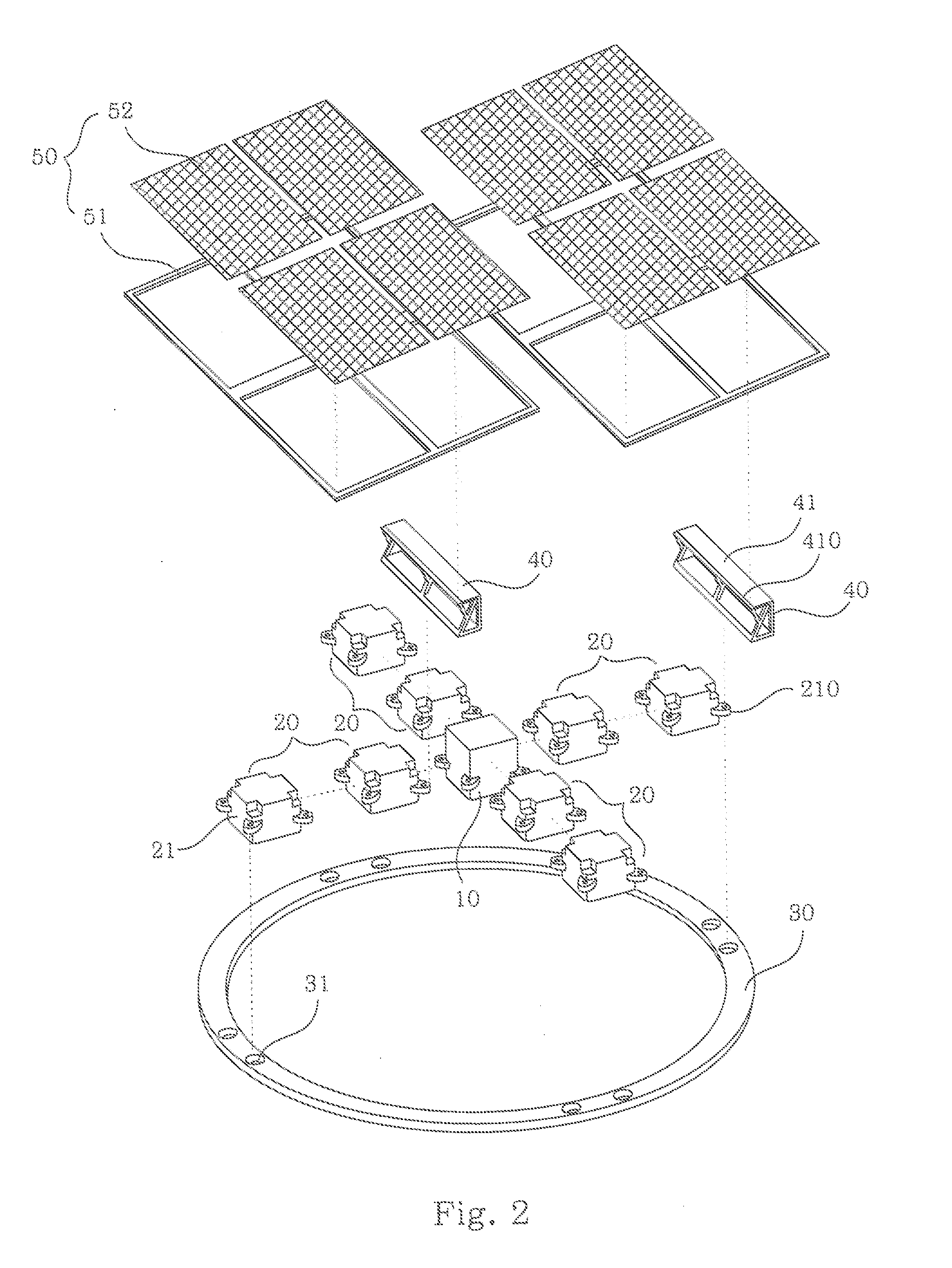
[0019]According to the multi-function solar power generating system of the present invention, the solar module is disposed on fluid to solve the problems of land utilization and heat dissipation if the solar module is disposed on land. In addition, it includes the function of tracking the sun, avoiding the worries of reduction in the power generating efficiency as the power generating system is moved to the water surface.

[0020]Please refer to FIG. 1 and FIG. 2, The structure according to the present embodiment comprises a convergence box 10, a plurality of buoy sets 20, a surrounding frame 30, one or more supporting frame 40, and one or more solar cell module 50. One end of the buoys 21 in the plurality of buoy set...


PUM


Abstract

The present Invention relates to a multi-function floating solar power generating system, which uses buoys to form buoy sets. A convergence box is used as the center for forming a cross structure, on which solar cell modules installed at an inclination angle of 10 to 15 degrees are carried. According to the present invention, a water-pumping unit below the buoy set is used for pumping the fluid. Then a spray unit is used for spraying the fluid and driving the system to rotate counterclockwise or clockwise, hence achieving the effect of tracking the sun. Alternatively, the fluid can be filtered or used for cleaning the solar cell module.

Description

FIELD OF THE INVENTION[0001]The present invention relates generally to a solar power generating system, and particularly to a multi-function floating solar power generating system having the functions of floating on the surface of a fluid, solar tracking for maintaining high power generating efficiency, water cleaning, and self-cleaning.BACKGROUND OF THE INVENTION[0002]The development of renewable energy resources, whether wind, geothermal, hydroelectric, or solar power generation, requires a certain area of land. Due to the continuous increase in population, the future supply of land will be tight and costly. The demand in land also threatens the environmental quality of human residences and the production conditions of food. In recent years, the development of floating solar energy has been promoted progressively worldwide, and thus enabling the application and development of solar power generation to grow rapidly.[0003]Although solar power generation is a renewable energy resourc...

Claims


Application Information

Patent Timeline
IPC IPC(8): H02S20/00B63B22/00B63B35/44H02S30/10
CPCH02S20/00H02S30/10B63B2035/4453B63B35/44B63B22/00B63B3/02H02S20/32H02S40/10Y02E10/50
Inventor YANG, HSI-HUNGMA, WEI-YANGYANG, TSUN-NENGLEE, CHENG-DAR
Owner INST OF NUCLER ENERGY RES ATOMIC ENERGY COUNCIL EXECUTIVE YUAN R O C
Learn More