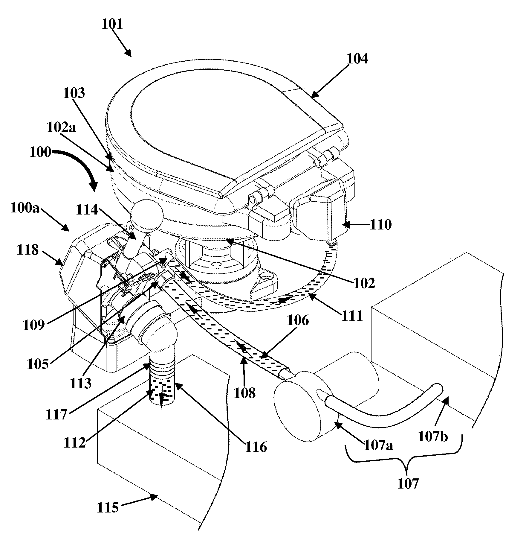
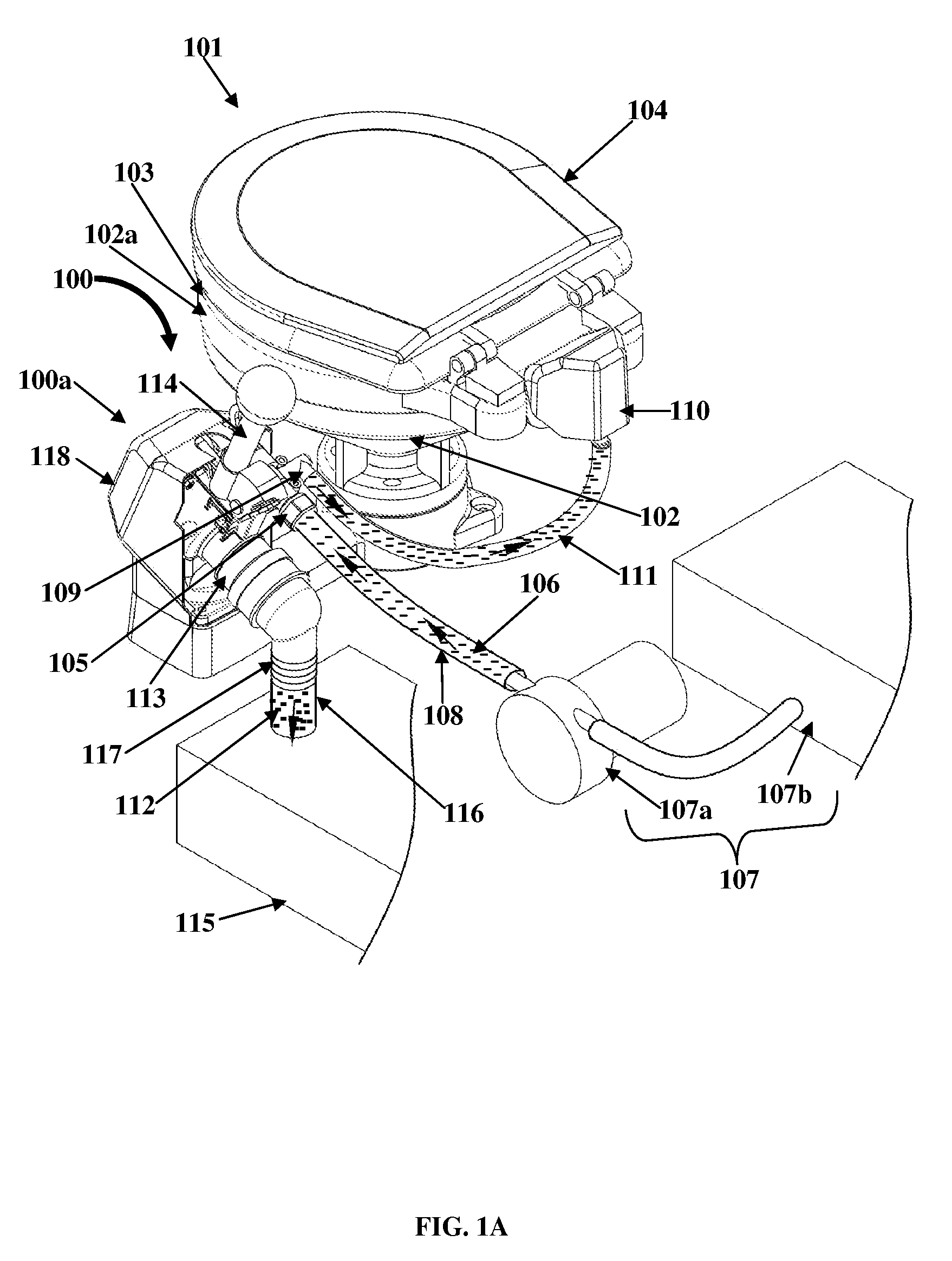
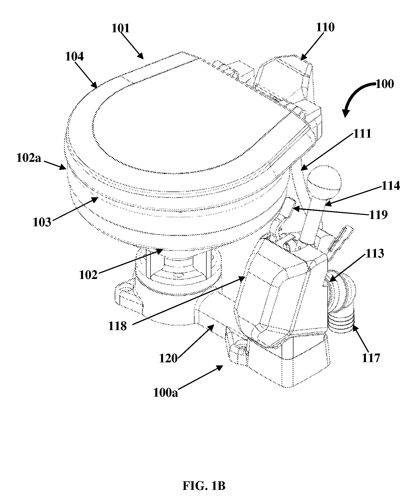
[0004]The apparatus disclosed herein addresses the above mentioned need for a manual toilet flushing apparatus comprising an integral, manually operated pressurized fresh water inlet valve assembly and a waste water discharge pump assembly that is operably isolated from the integral, manually operated pressurized fresh water inlet valve assembly for precluding waste water discharged from a toilet bowl via the waste water discharge pump assembly from contaminating pressurized fresh water transferred to the toilet bowl via the integral, manually operated pressurized fresh water inlet valve assembly, thereby reducing odors in and around the toilet bowl and scale formation in toilet related plumbing. The “manual toilet flushing apparatus” disclosed herein is hereinafter referred to as a “flushing apparatus”. The “integral, manually operated pressurized fresh water inlet valve assembly” disclosed herein is hereinafter referred to as an “integral inlet valve assembly”. The “waste water discharge pump assembly” disclosed herein is hereinafter referred to as a “discharge pump assembly”.
[0006]In an embodiment, the integral inlet valve assembly of the flushing apparatus disclosed herein further comprises a filter screen fixedly attached to the pressurized fresh water inlet port of the integral inlet valve assembly. The filter screen traps microparticulates from the pressurized fresh water. The check valve of the integral inlet valve assembly is positioned in the inlet valve cavity of the inlet valve body and proximal to the pressurized fresh water inlet port. The check valve opens and closes to direct the flow of the pressurized fresh water from the pressurized fresh water inlet port into the inlet valve cavity. The check valve is removably positioned within the inlet valve cavity to facilitate repair and maintenance of the integral inlet valve assembly. The lever of the integral inlet valve assembly is positioned proximal to a distal end of the inlet valve cavity. The lever is easily accessible and actuates the check valve to allow rinse water or the pressurized fresh water to rinse the toilet bowl independent of the discharge pump assembly. That is, the actuation of the check valve by the lever for rinsing the toilet bowl is independent of the discharge of the waste water from the toilet bowl through the discharge pump assembly. The first plunger of the integral inlet valve assembly is positioned in the inlet valve cavity and is operably connected between the lever and the second plunger. The first plunger, in communication with the lever, actuates the second plunger.
[0007]The second plunger of the integral inlet valve assembly is positioned in the inlet valve cavity of the inlet valve body and is operably connected between the first plunger and the check valve. The second plunger, in communication with the first plunger, actuates the check valve to open and close the check valve. In an embodiment, the integral inlet valve assembly further comprises a diaphragm member positioned between the first plunger and the second plunger. The diaphragm member is fixedly connected to the opposing walls of the inlet valve cavity. The diaphragm member isolates the first plunger from the second plunger. The outlet port of the integral inlet valve assembly extends from the inlet valve body and is in fluid communication with the inlet valve cavity. The outlet port directs the flow of the pressurized fresh water from the inlet valve cavity to the rim of the toilet bowl through an outlet hose removably connected to and in fluid communication with the outlet port. In an embodiment, a vacuum breaker is positioned above the rim of the toilet bowl. The vacuum breaker is in fluid communication with the outlet hose and prevents a back flow of the pressurized fresh water to the integral inlet valve assembly from the rim of the toilet bowl via the outlet hose.
[0008]The discharge pump assembly of the flushing apparatus disclosed herein comprises a waste water inlet port, a discharge pump body, a retractable handle, a connecting rod, a piston, and a discharge port. The waste water inlet port of the discharge pump assembly is positioned at a lower section of the discharge pump body. The waste water inlet port receives the waste water from the toilet bowl via a waste water pipe. The discharge pump body of the discharge pump assembly comprises a pump cavity in fluid communication with the waste water pipe via the waste water inlet port to transfer the waste water from the toilet bowl to the discharge port. The retractable handle of the discharge pump assembly is positioned above the pump cavity of the discharge pump body. In an embodiment, the retractable handle is secured within a sleeve of the connecting rod. The retractable handle retracts in a substantially vertical direction within the sleeve in an upward direction and a downward direction. In an embodiment, the sleeve is configured as an integral socket to receive the retractable handle. The connecting rod of the discharge pump assembly is positioned within the pump cavity and is hingedly connected between the retractable handle and the piston. The connecting rod, in communication with the retractable handle, actuates the piston in a forward direction and a backward direction. The piston of the discharge pump assembly is positioned within the pump cavity and is operably connected to the connecting rod. The piston is actuated, for example, in the backward direction by the connecting rod which suctions the waste water into the pump cavity. The piston is actuated, for example, in the forward direction by the connecting rod which discharges the waste water through the discharge port. In an embodiment, the piston within the discharge pump body is oriented at a predefined inclination to a vertical axis such that the piston is in line with the discharge port to prevent clogging of the pump cavity and the discharge port. The discharge port of the discharge pump assembly extends from the discharge pump body and is in fluid communication with the pump cavity. The discharge port discharges the waste water from the pump cavity to a waste holding tank.
[0009]In an embodiment, the discharge pump assembly of the flushing apparatus disclosed herein further comprises a flapper valve member positioned proximal to the lower section of the pump cavity of the discharge pump body and secured to the waste water inlet port, for example, via a thread member. The flapper valve member opens during movement of the piston in the backward direction to transfer the waste water from the lower section of the pump cavity to an upper section of the pump cavity via the waste water inlet port. The flapper valve member closes during movement of the piston in the forward direction to discharge the waste water contained in the upper section of the pump cavity through the discharge port. In an embodiment, the flapper valve member prevents a back flow of the waste water to the toilet bowl via the waste water pipe in fluid communication with the pump cavity of the discharge pump body by closing the waste water inlet port.
[0010]In an embodiment, the integral inlet valve assembly and the discharge pump assembly of the flushing apparatus disclosed herein are positioned in close proximity behind a cover member for facilitating ease of operation of the flushing apparatus and a clean installation of the flushing apparatus. The discharge pump body of the discharge pump assembly is oriented at a predefined inclination to a vertical axis for facilitating a flexible pumping action of the piston in communication with the retractable handle. In an embodiment, the discharge pump assembly further comprises a piston cap operably connected proximal to a rear surface of the piston of the discharge pump assembly. The piston cap secures a circular diaphragm to the piston. In an embodiment, a predefined geometry of the piston maintains a consistent stroke for the circular diaphragm.