
A precision surical guidance tool system and delivery method for implementing dental implants

a dental implant and precision technology, applied in dental tools, dental surgery, medical science, etc., can solve the problems of bone tissue necrosis, limited target bone site for the proper placement of dental implants, and even more difficult for the practitioner to achiev

Inactive Publication Date: 2016-03-24
GST
View PDF23 Cites 10 Cited by
  • Summary
  • Abstract
  • Description
  • Claims
  • Application Information

AI Technical Summary

Benefits of technology

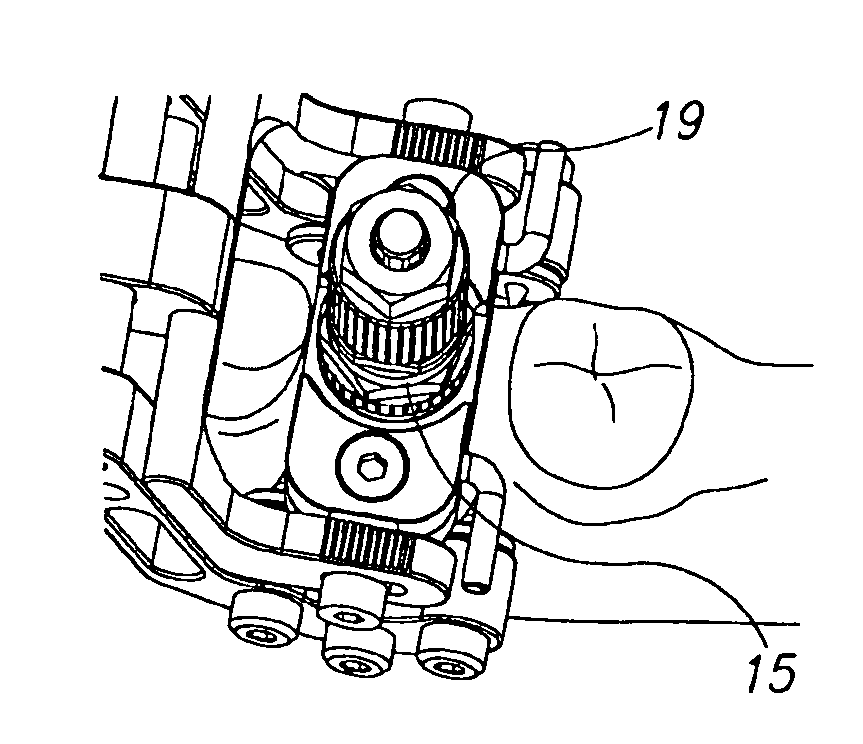
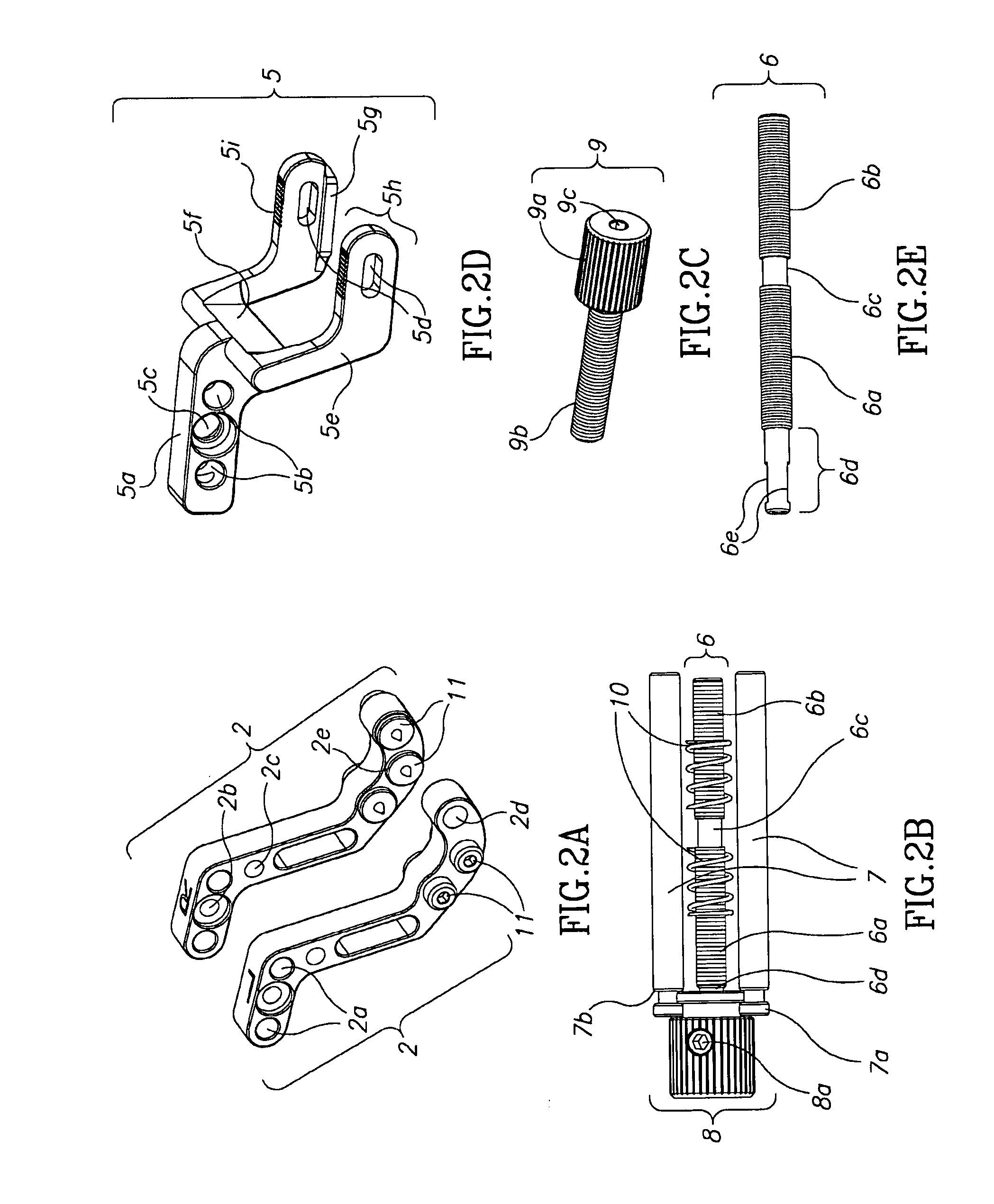
The patent describes a surgical clamp and gage tools for dental implant procedures. The clamp has adjustable positioning elements for securing it to the bone or gums, and can hold separate components for drilling and inserting the implant. The gage has a measuring bit that can accurately measure the thickness of the gum tissue overlooking the jawbone, and has adjustable settings for accurate measurements. These tools help make the dental implant procedure more efficient and effective.

Problems solved by technology

This means that the target bone site for the proper placement of a dental implant is very limited and requires the practitioner who wishes to place dental implants safely to exercise considerable care performing the implant procedure after first having acquired a high degree of skill level and clinical experience.
This becomes even more difficult for the practitioner when attempting to place multiple dental implants in the same jawbone.
It is well established medical fact that overheating bone tissue is highly destructive to surrounding bone tissue and leads invariably to necrosis of bone tissue, a highly undesirable outcome.
This process is both time-consuming and expensive for the dental practitioner in terms of delay of delivery of treatment to the patient, fees to the laboratory, and the costs of the imaging and software licenses.
It can be appreciated that this required method for surgically securing the stent is quite invasive to the patient and results in significant post-operative pain and healing.

Method used


Image

  • A precision surical guidance tool system and delivery method for implementing dental implants
  • A precision surical guidance tool system and delivery method for implementing dental implants
  • A precision surical guidance tool system and delivery method for implementing dental implants

Examples


Embodiment Construction

[0076]The following description is presented to enable one of ordinary skill in the art to make and use the invention as provided in the context of a particular application and its requirements. Various modifications to the described embodiments will be apparent to those with skill in the art, and the general principles defined herein may be applied to other embodiments. Therefore, the present invention is not intended to be limited to the particular embodiments shown and described, but is to be accorded the widest scope consistent with the principles and novel features herein disclosed. In other instances, well-known methods, procedures, and components have not been described in detail so as not to obscure the present invention.

[0077]Embodiments of the present invention enable dental implant treatments using one time or reusable surgical clamp apparatus and guidance system. Means and methods are herein provided for the preparation and insertion into bony tissue of standard implants...


PUM


Abstract

A system, apparatus, device, tools, kit and method is provided for the preparation of the jawbone and insertion of dental implants. The apparatus includes a universal and reusable clamping device and removable components for the clamp which allow for precision surgical preparation and implantation of dental implants into the jawbone. According to some embodiments, an apparatus is provided that includes a platform; one or more frames connected to the platform, wherein the frames include a clamp arm that extend to opposing sides of the bone; and one or more fixation cleats on each arm; wherein the apparatus includes one or more features for positioning the platform, for changing a position of the platform, for changing an angle of a component of the platform or any combination thereof, following the securing of the clamp arms to the bone and prior to the procedure.

Description

FIELD OF THE INVENTION[0001]The present invention relates generally to dental implants and more particularly to an improved means and method for the preparation and insertion of dental implants.BACKGROUND OF THE INVENTION[0002]A dental implant is an artificial prosthesis normally comprised of a single cylindrical component to replace the missing root structure of a natural tooth that has been lost. This standard implant is typically inserted into the jawbone by threading or screwing it into a prepared hollowed out bony site in the jawbone called in the field an osteotomy. The prepared osteotomy typically has a diameter that corresponds to the body dimensions of the implant without its threads and the threads of the implant engage (self-tap) the vertical inner walls of the osteotomy as it is screwed into place. The implant typically remains buried in the bone (endosseous) for a period of time to allow for “osseo-integration” or the growth and adhesion of natural bone around all the e...

Claims


Application Information

Patent Timeline
Patent Type & Authority Applications(United States)
IPC IPC(8): A61C1/08A61C8/00
CPCA61C8/0089A61C1/084
Inventor SANDERS, DANIELSPECTOR, BEN, ZION
Owner GST
Learn More