
Brake Disc Assembly for a Wheel

a technology of brake discs and rotating parts, which is applied in the direction of brake discs, braking elements, brake types, etc., to achieve the effect of less susceptible to wear-based damag

Active Publication Date: 2016-03-17
WABTEC HLDG CORP
View PDF5 Cites 18 Cited by
  • Summary
  • Abstract
  • Description
  • Claims
  • Application Information

AI Technical Summary

Benefits of technology

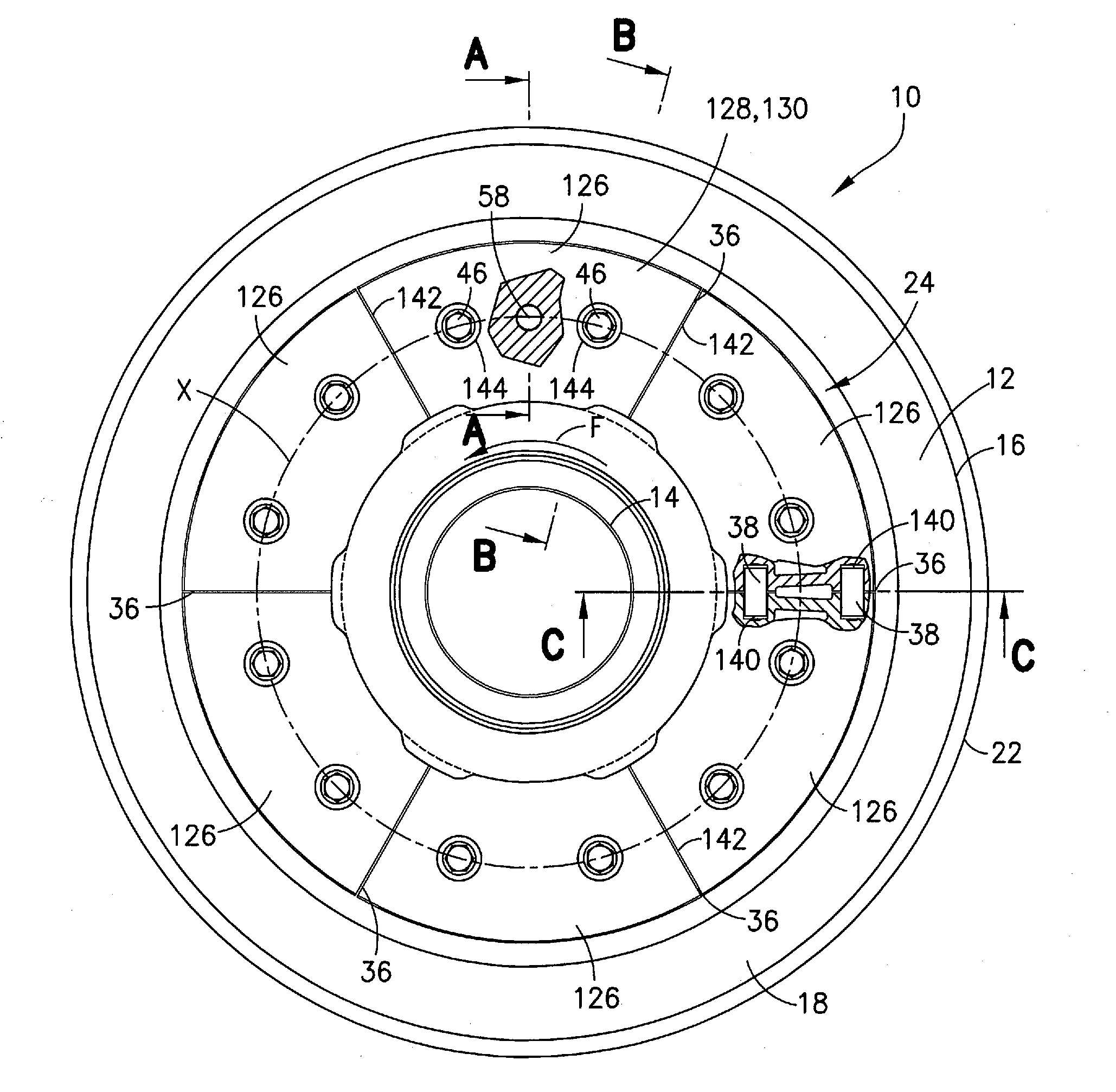
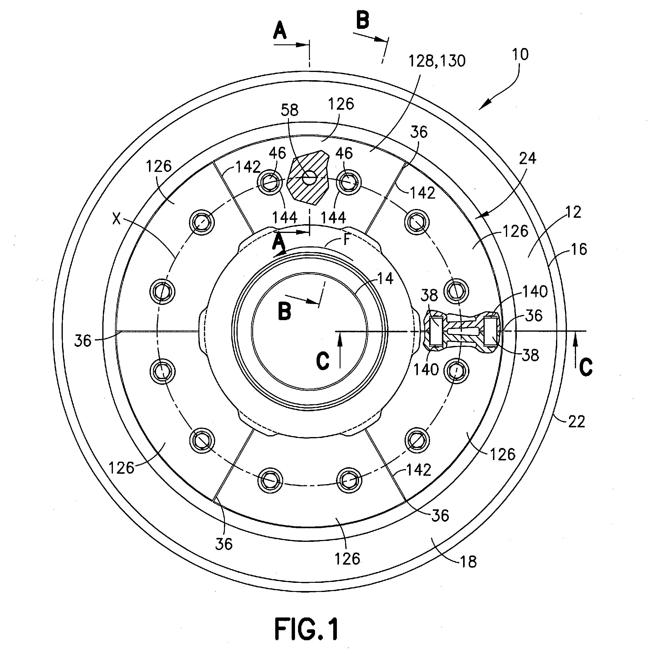
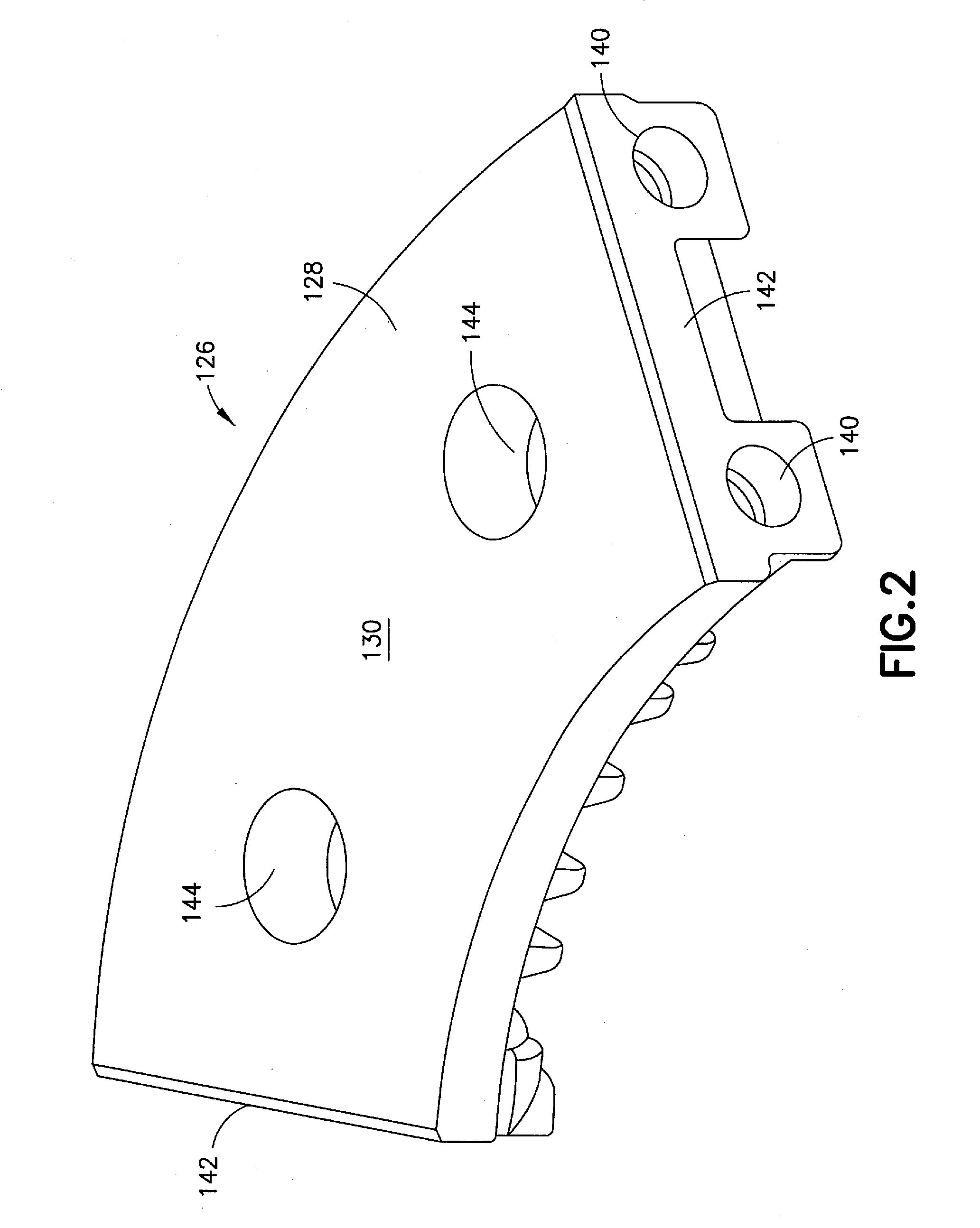
The present invention is a brake assembly for vehicles that includes a segmented brake disc that is less susceptible to damage caused by thermal expansion and operates more quietly than known alternative systems. The brake disc includes a plurality of transverse through holes and each segment includes two sockets on each radial end of the segment. This allows for slidable joining of brake parts and easy replacement of brake shoes. The brake assembly is less prone to wear-based damage and operates more efficiently in braking vehicles.

Problems solved by technology

Furthermore, while the brake disc is permitted to expand, movement of individual segments in the circumferential and radial directions is restricted to prevent a brake shoe from contacting misaligned segments.

Method used


Image

  • Brake Disc Assembly for a Wheel
  • Brake Disc Assembly for a Wheel
  • Brake Disc Assembly for a Wheel

Examples


Embodiment Construction

[0027]The following description is provided to enable those skilled in the art to make and use the described embodiments contemplated for carrying out the invention. Various modifications, equivalents, variations, and alternatives, however, will remain readily apparent to those skilled in the art. Any and all such modifications, variations, equivalents, and alternatives are intended to fall within the spirit and scope of the present invention. Further, for purposes of the description hereinafter, the terms “end”, “upper”, “lower”, “right”, “left”, “vertical”, “horizontal”, “top”, “bottom”, “lateral”, “longitudinal”, and derivatives thereof shall relate to the invention as it is oriented in the drawing figures.

[0028]However, it is to be understood that the invention may assume various alternative variations and step sequences, except where expressly specified to the contrary. It is also to be understood that the specific devices and processes illustrated in the attached drawings, and...


PUM


Abstract

A brake disc for providing a braking surface on a rotating body, such as a railway wheel is provided. The brake disc includes a plurality of arcuate segments (126) arranged to form a ring and a plurality of joining elements (38) for connecting the segments to adjacent segments. Each segment includes: an inner side configured to contact a surface of a wheel; an outer side having a braking surface for contacting a braking mechanism; at least one socket (140) on each radial end (142) of the segment (126) for receiving one of the plurality of joining elements (38); and a groove on the inner side of the segment configured to receive a coupling member to form a pivot joint (58) for positioning the segment (126) on the surface of the wheel.

Description

CROSS REFERENCE TO RELATED APPLICATION[0001]This application claims priority to U.S. Provisional Application No. 61 / 811,316 filed Apr. 12, 2013, and is incorporated herein in its entirety.BACKGROUND OF THE INVENTION[0002]1. Field of the Invention[0003]The present disclosure relates to a brake disc for a rotating member, such as a wheel, and, more specifically, to an annular brake disc formed from a plurality of interconnected brake disc segments.[0004]2. Description of Related Art[0005]Brake discs are affixed to wheels for the purpose of providing a smooth, hard contact surface that can be contacted by a brake shoe or pad controlled by a brake mechanism, such as a brake jaw. When contact between the disc and shoe or pad is established, friction between the elements is sufficient to reduce or entirely inhibit rotation of the wheel. Disc brakes are commonly used in a variety of applications including, for example, industrial machines, such as cranes and lifts, as well as in conveying ...

Claims


Application Information

Patent Timeline
IPC IPC(8): F16D65/12F16D65/847
CPCF16D65/124F16D65/121F16D2065/1392F16D2065/1312F16D2065/1328F16D65/847F16D65/123F16D65/128F16D2065/1316F16D2065/132F16D2065/1332
Inventor BOFFELLI, ROBERTO
Owner WABTEC HLDG CORP
Learn More