Method for characterizing the seat of a railroad track, device for viewing the inside of a ground and assembly for characterizing the seat of a railroad track comprising such a device

a technology for railroad tracks and seats, which is applied in the direction of television systems, instruments, and ways. it can solve the problems of increasing maintenance costs, accelerating wear of track components, and avoiding systemic errors in measurement acquisition, and reducing the performance and exploitation time of drilling operations

Active Publication Date: 2016-03-17
SOL SOLUTION
View PDF33 Cites 12 Cited by
  • Summary
  • Abstract
  • Description
  • Claims
  • Application Information

AI Technical Summary

Benefits of technology

[0014]The invention more particularly aims to resolve these drawbacks by proposing a method for characterizing the seat of a railroad track making it possible to offset the technical and practical difficulties of implementing drilling using the current means.
[0024]Owing to the invention, systematic errors in the measurement acquisition are avoided, since the depth at which the images are taken by the camera is measured automatically. Furthermore, the performance and exploitation time of the drilling operations is shortened, since the data obtained for the geo-endoscopic and penetrometric tests are automatically coupled and analyzed.

Problems solved by technology

The speed, the weight of the trains and the density of the traffic have increased considerably with the technological progress in recent years, which creates accelerated wear of the track components, in particular the ballast.
Thus, the track repair operations, as well as the discontinuous and differential subsidence, are more frequent, which causes a considerable increase in maintenance costs and, in some cases, early renewal.
Furthermore, it is considered that the maintenance of the ballast and the geometry of the track represent approximately half of the overall maintenance cost for railroad tracks, which is in particular due to the fact that the work is done during the night.
However, there has been no progress regarding the protection of the ballast.
However, the latter remains the fastest-deteriorating element in a railroad track.
This deterioration is accelerated by stresses due to traffic, but also by those due to maintenance work, such as packing, which have become more frequent.
The creation of these two layers within a track section poses mechanical and hydraulic stability problems, such as poor drainage, breaking of the grains of the “healthy” ballast layer, packing of the track, or deformation of the platform.
The problem that arises is to efficiently and cost-effectively establish a diagnosis of the railroad track condition, in particular aiming to detect the “polluted ballast” and “intermediate” layers.
This monitoring technique is not the most appropriate, since only one coring train exists on the National Railway Network and the cost of this type of intervention is high.
This technique further lacks precision in measuring the thicknesses of the layers, since there is a risk of shifting during the raising of the core bit, especially for sandy materials.
Lastly, this technique does not make it possible to measure the resistance of the ground.
Although interesting, this monitoring technique is relatively time-consuming due to the manual transcription of the data, and there is no automatic and continuous measurement regarding the depth at which the images and video of the geo-endoscope are recorded.
The diagnosis of the ground state is based in part on the technician's interpretation, which may lead to errors.
This measurement in fact appears to be useless in this case, since the geo-endoscopic test does not seek to determine the depth of the different layers of the filtering medium.

Method used


Image

  • Method for characterizing the seat of a railroad track, device for viewing the inside of a ground and assembly for characterizing the seat of a railroad track comprising such a device
  • Method for characterizing the seat of a railroad track, device for viewing the inside of a ground and assembly for characterizing the seat of a railroad track comprising such a device
  • Method for characterizing the seat of a railroad track, device for viewing the inside of a ground and assembly for characterizing the seat of a railroad track comprising such a device

Examples


Embodiment Construction

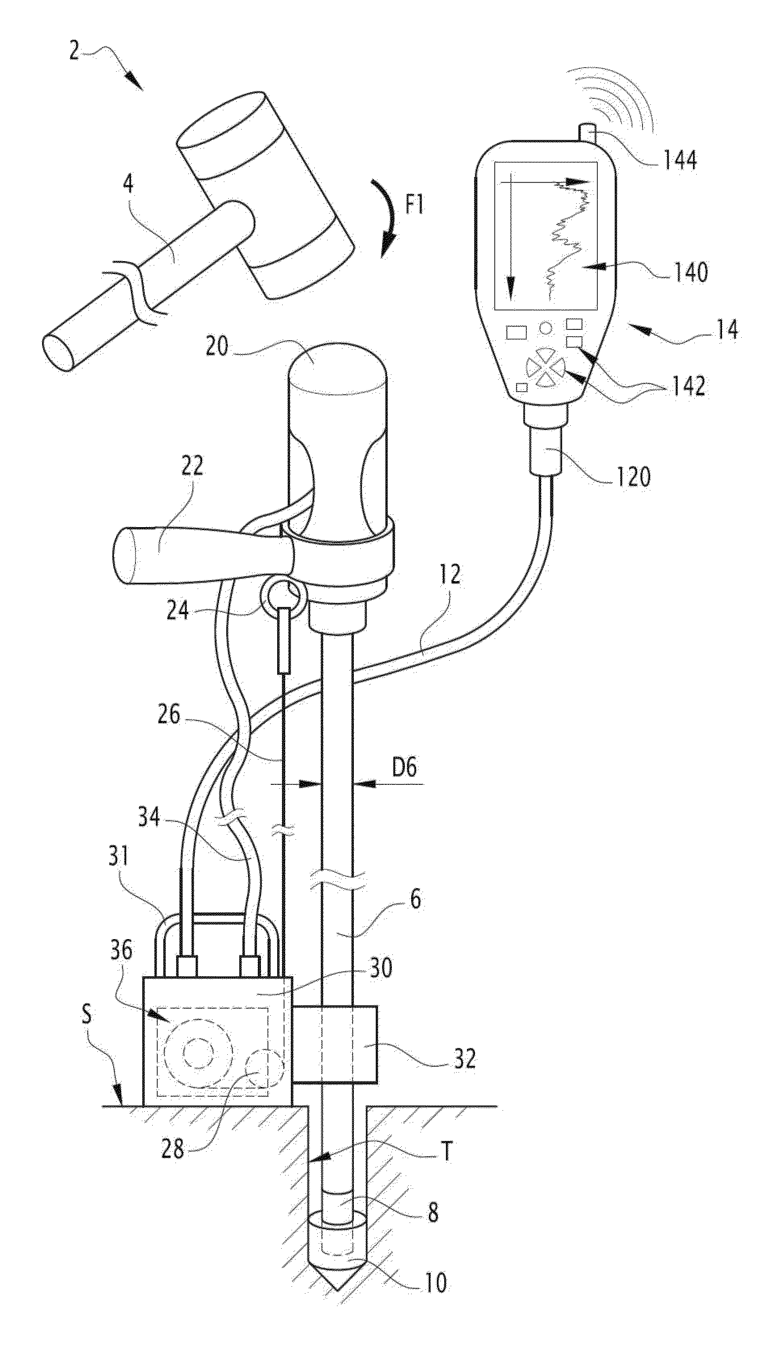
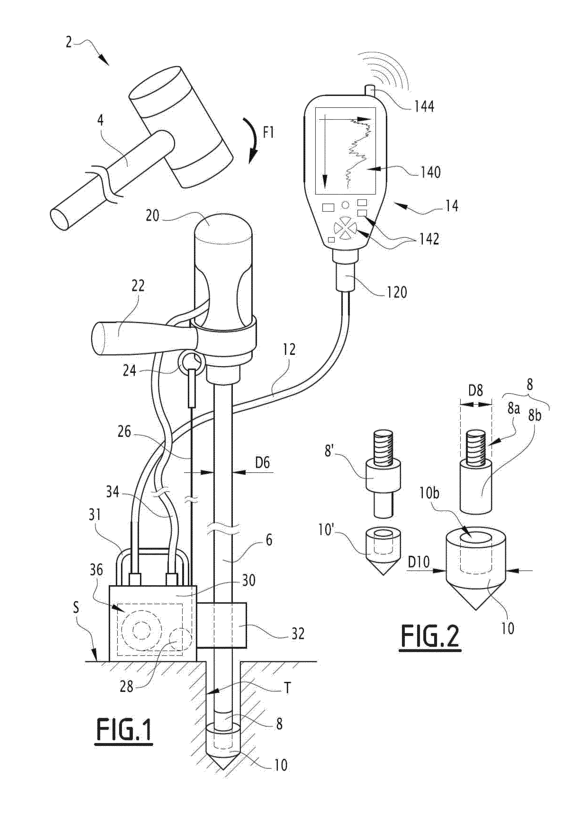
[0056]FIG. 1 shows a light dynamic penetrometer 2 of the Panda type (registered trademark). This penetrometer 2 has a mass of less than 20 kg, such that it is easy for an operator to transport. This penetrometer 2 is also relatively compact, which facilitates interventions with restricted access. It can also be folded up quickly in case of emergency.

[0057]The dynamic penetrometer 2 extends globally along an axis Z2 which, during a test, is vertical. It includes a ram head 20 in its upper part suitable for receiving a hammer strike 4 to push a train of rods 6 into the ground. The penetrometer 2 also comprises a handle 22 to keep the train of rods 6 straight during the hammer strike. The train of rods 6 extends straight along the axis Z2 and comprises one or more cylindrical rods assembled to one another. Each rod of the train of rods 6 has a diameter D6, for example of approximately 14 mm. A tip holder 8 is screwed to a lower end of the train of rods 6. As its name indicates, the tip...


PUM

PropertyMeasurementUnit
massaaaaaaaaaa
diameter D6aaaaaaaaaa
diameteraaaaaaaaaa

Abstract

This method makes it possible to characterize the seat of a railroad track through penetrometric and geo-endoscopic tests. It includes steps consisting of striking ram head of a light dynamic penetrometer to drive the tip of a train of rods into the seat, measuring the strength of the seat as a function of the pushing in depth of the train of rods, removing the train of rods from the seat, pushing a tube into a hole left by the train of rods, and sliding an image-recording camera inside the tube. The method includes additional automated steps consisting of measuring the position of the camera while it slides inside the tube, i.e., the dep that which the images are recorded, and couplingan analysis of the recorded images as a function of the depth with the strength measurements of the seat to characterize the different layers of the seat.

Description

FIELD OF THE INVENTION[0001]The invention relates to a method for characterizing seat layers of a railroad track by coupling a penetrometric test and a geo-endoscopic test.[0002]The invention aims to establish a geotechnical diagnosis and to obtain, as precisely as possible, parameters making it possible to characterize the nature and hydric state of the different seat layers of a railroad track in use. This in particular makes it possible to assess whether renewal or repair work is necessary on the track.[0003]The invention also relates to a device for viewing the inside of a ground, that device commonly being called “geo-endoscope”. The invention lastly relates to an assembly for characterizing a ground, comprising such a device, a light dynamic penetrometer of the Panda type (registered trademark) and a processing unit.BACKGROUND OF THE INVENTION[0004]Ballasted railroad tracks, developed nearly two centuries ago, are built using a set of elements designed to support the weight of...

Claims


Application Information

Patent Timeline
Patent Type & Authority Applications(United States)
IPC IPC(8): E01B35/00E01B1/00G01N3/42H04N5/225
CPCE01B35/00E01B1/00H04N2005/2255H04N5/225G01N3/42G01N3/48E02D1/022H04N23/00H04N23/555
Inventor GOURVES, ROLANDHADDANI, YOUNES
Owner SOL SOLUTION
Why Eureka
Try Eureka