
Electric arc torch with cooling conduit

a technology of electric arc torch and cooling conduit, which is applied in the field of torch, can solve the problems of cooling conduit warpage, unsatisfactory temperature gradient, and inability to achieve uniform temperature across the cooling conduit,

Active Publication Date: 2016-03-17
LINCOLN GLOBAL INC
View PDF37 Cites 37 Cited by
  • Summary
  • Abstract
  • Description
  • Claims
  • Application Information

AI Technical Summary

Benefits of technology

This patent describes a cooling system for an electric arc torch, which helps to control the temperature of the torch during use. The cooling system includes a cooling conduit that has a central axial bore for conveying shielding gas, and longitudinal cooling channels within the conduit wall that extend from a first end to a second end. The cooling conduit also has a first manifold cap and a second circumferential channel, and a second manifold cap and a third circumferential channel, which form part of the conduit wall. These channels allow cooling liquid to flow through the conduit and cool the torch. The electric arc torch also includes an electrical conductor that is located within the central axial bore of the cooling conduit. The cooling system helps to control the temperature of the torch, which is important for safe and effective welding.

Problems solved by technology

This can result in undesirable temperature gradients across the cooling conduit, with one side of the cooling conduit near the cold water supply passage being cooler than the other side of the cooling conduit near the warm water return passage.
Temperature gradients across the cooling conduit in turn can lead to a slight warping of the cooling conduit due to differing amounts of temperature-induced expansion and contraction of the cooling conduit.
Warping of the cooling conduit can result in the tip of the torch being misaligned or out of an expected position, which can decrease the precision of the resulting weld or cut, in particular during robotic control of the torch.

Method used


Image

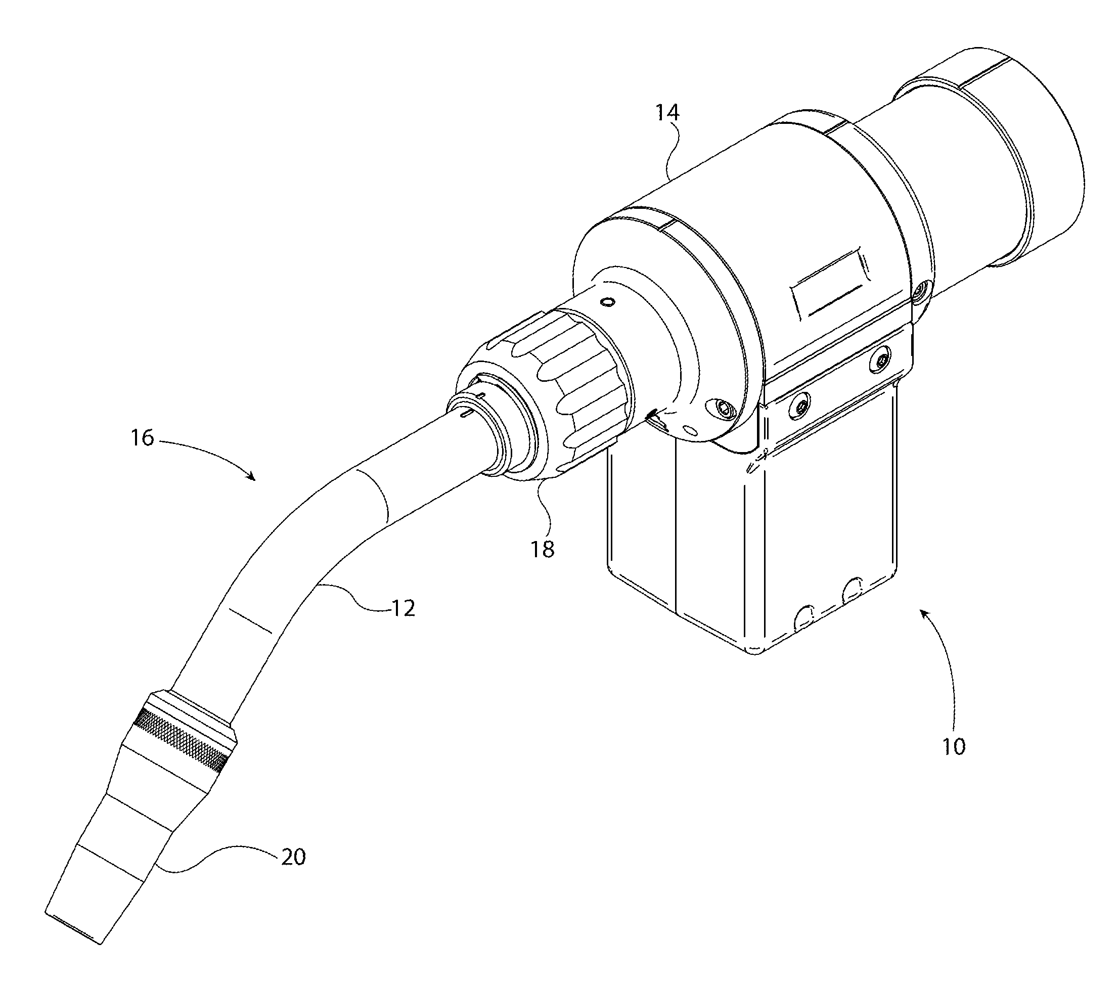
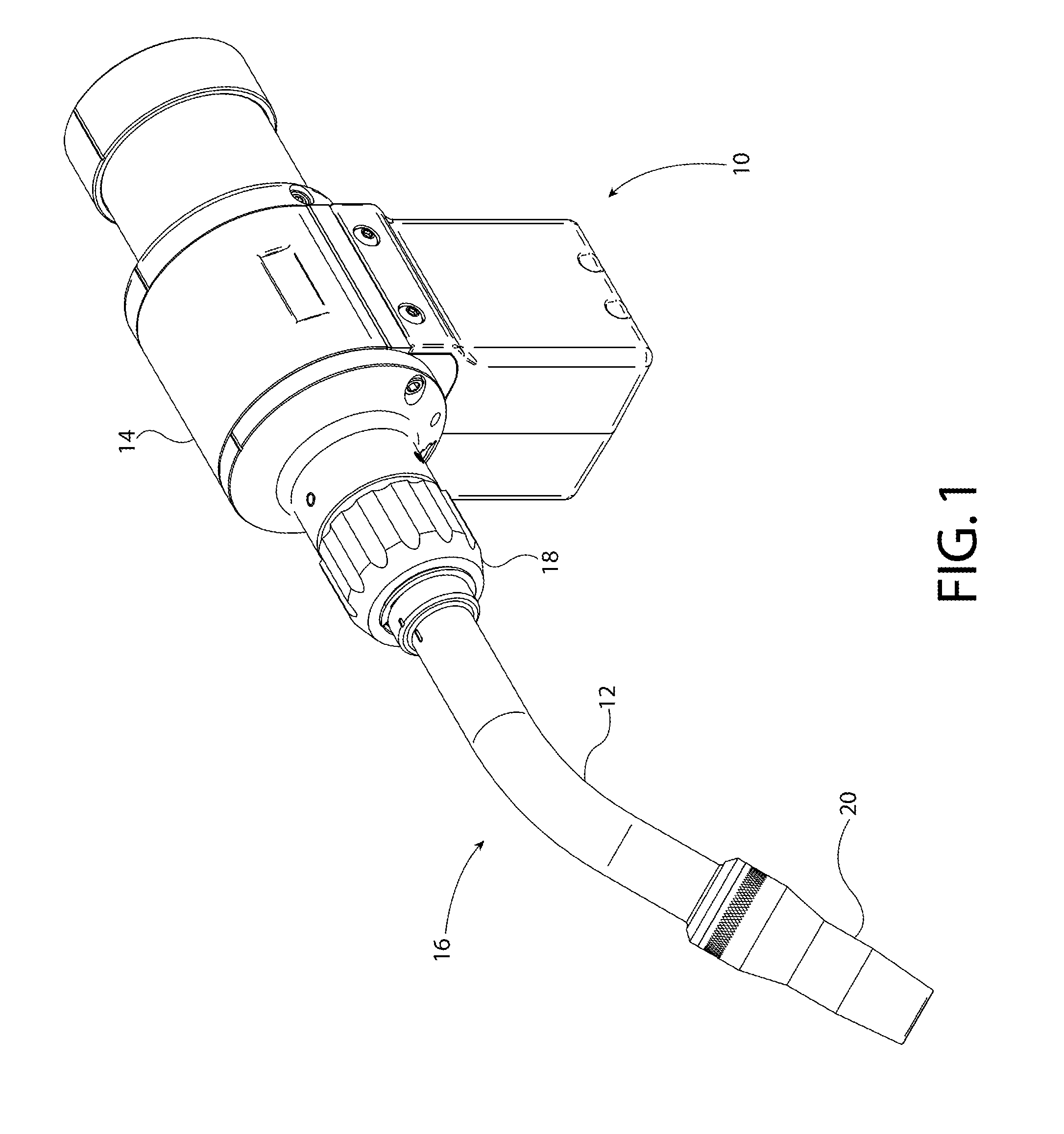
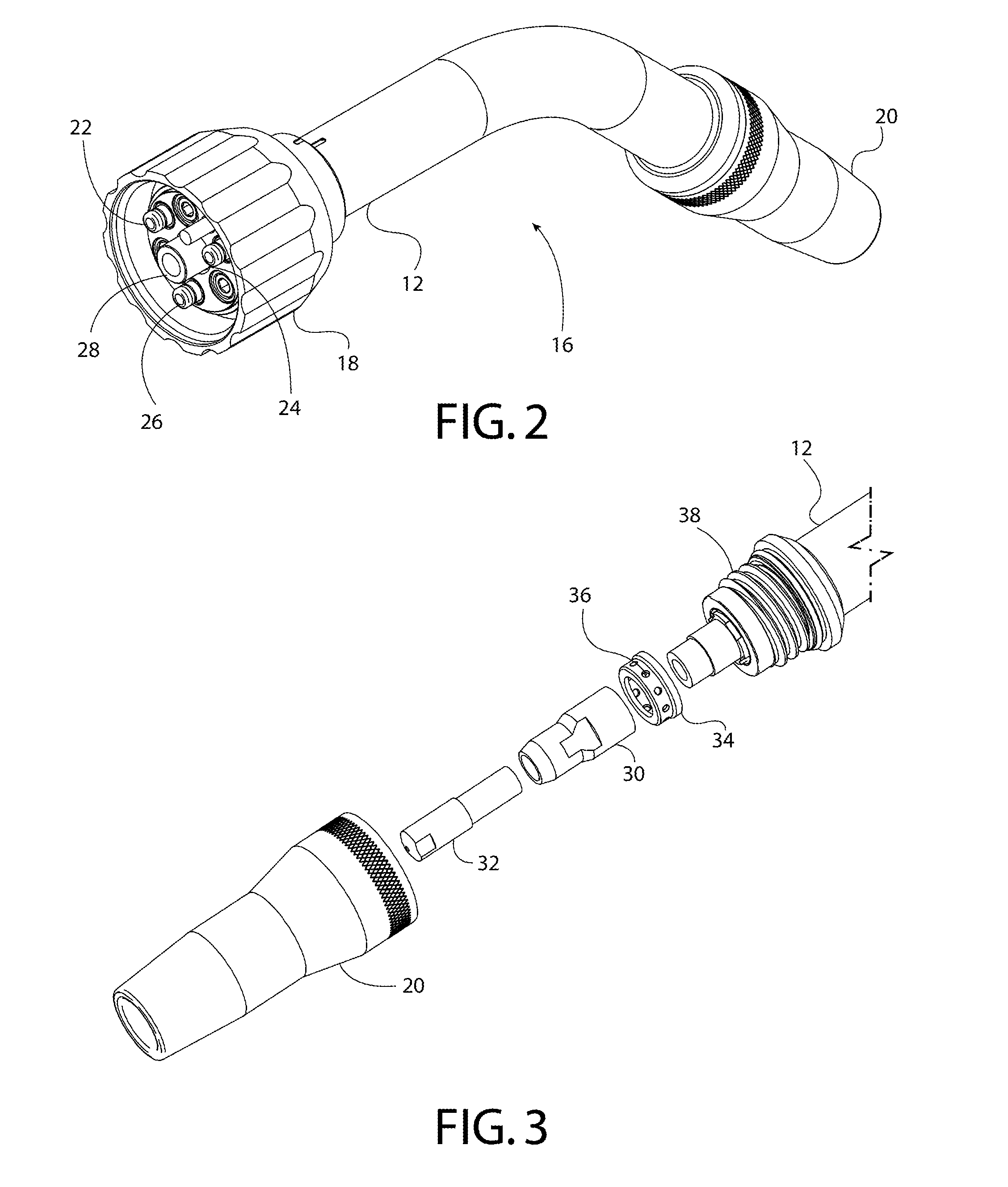
  • Electric arc torch with cooling conduit
  • Electric arc torch with cooling conduit
  • Electric arc torch with cooling conduit

Examples


Embodiment Construction

[0015]The present subject matter relates to electric arc torches, such as arc welding torches, plasma cutters, and the like. In particular, the present subject matter relates to liquid-cooled torches and portions of torches that convey cooling liquid. The present subject matter will now be described with reference to the drawings, wherein like reference numerals are used to refer to like elements throughout. It is to be appreciated that the various drawings are not necessarily drawn to scale from one figure to another nor inside a given figure, and in particular that the size of the components are arbitrarily drawn for facilitating the understanding of the drawings. In the following description, for purposes of explanation, numerous specific details are set forth in order to provide a thorough understanding of the present subject matter. It may be evident, however, that the present subject matter can be practiced without these specific details. Additionally, other embodiments of the...


PUM

PropertyMeasurementUnit
temperatureaaaaaaaaaa
electrically conductiveaaaaaaaaaa
sizeaaaaaaaaaa

Abstract

An electric arc torch includes a torch base, and a cooling conduit having a conduit wall forming a central axial bore and having a plurality of longitudinal cooling channels spaced circumferentially around the bore. The cooling channels extend through the conduit wall from a first end portion to a second end portion of the conduit. The cooling channels include both a plurality of cooling liquid distribution channels and a plurality of cooling liquid return channels alternately arranged within the conduit wall. The conduit includes a circumferential cooling liquid manifold in fluid communication with each of the cooling liquid distribution channels, a circumferential return manifold in fluid communication with each of the cooling liquid return channels, and a circumferential recirculation manifold in fluid communication with each of the cooling liquid distribution and return channels such that the cooling liquid distribution and return channels are in fluid communication through the circumferential recirculation manifold.

Description

BACKGROUND[0001]1. Field of the Disclosure[0002]The present invention relates to torches for generating electric arcs, and in particular to liquid-cooled welding torches.[0003]2. Description of Related Art[0004]Conventional liquid-cooled torches for generating electric arcs have a cooling tube or conduit located between the base or handle of the torch and the tip of the torch (from which the electric arc is emitted). The torch is heated by the arc during welding, plasma cutting, etc. To remove the heat from the welding torch, cooling liquid, such as water, is circulated through the cooling conduit. The cooling conduit typically has at least two longitudinal cooling passages extending toward the tip of the torch. One of the passages is used to convey cold water toward the tip of the torch, and the other passage is used to return heated water to a chiller or waste receiver. The passages are often on opposite sides of the cooling conduit (e.g., spaced approximately 180° apart). This ca...

Claims


Application Information

Patent Timeline
Patent Type & Authority Applications(United States)
IPC IPC(8): B23K37/00B23K9/16B23K9/32
CPCB23K37/003B23K9/323B23K9/164B23K9/173B23K9/285
Inventor KACHLINE, JEFFREY L.DINGELDEIN, MATTHEW
Owner LINCOLN GLOBAL INC
Learn More