
Electric drive system for mining haul truck

a technology for mining haul trucks and electric drive systems, which is applied in the direction of electric motor propulsion transmissions, locomotive transmissions, electric devices, etc., can solve the problems that one engine and one generator may not be able to produce the required power

Inactive Publication Date: 2016-03-03
SIEMENS IND INC
View PDF5 Cites 2 Cited by
  • Summary
  • Abstract
  • Description
  • Claims
  • Application Information

AI Technical Summary

Benefits of technology

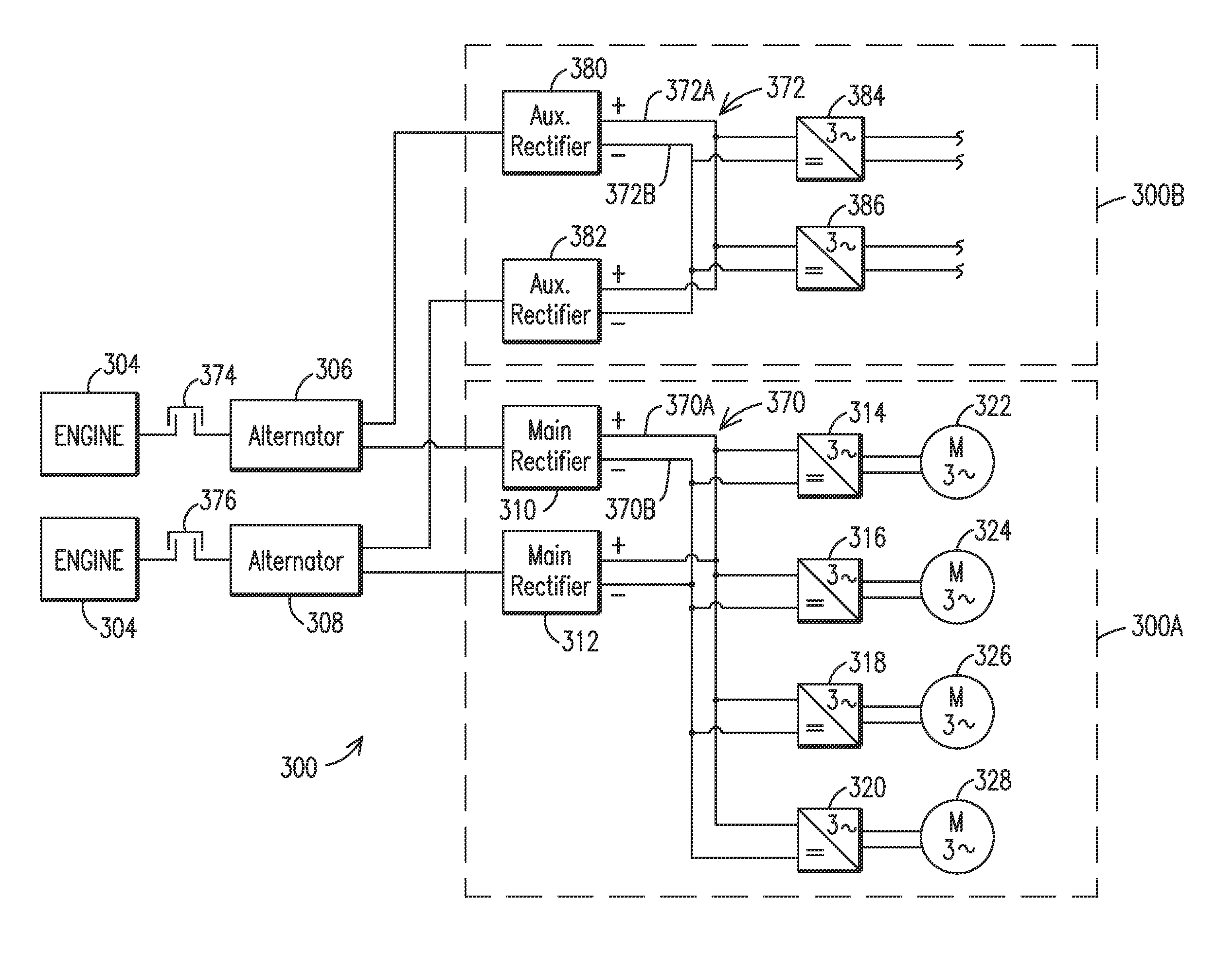
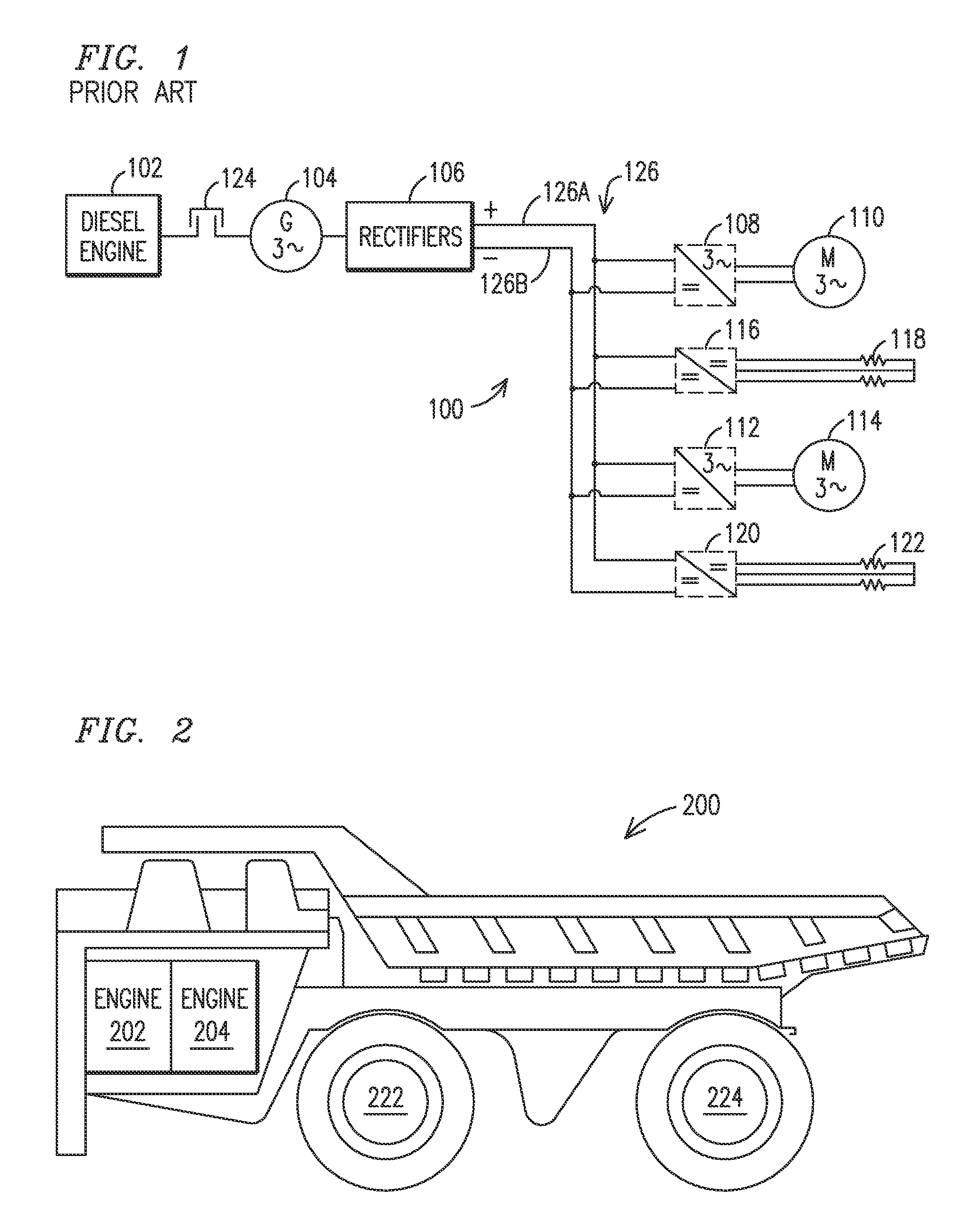
The present invention relates to an electric drive system for a vehicle, specifically an off-highway vehicle like a mining haul truck. The system includes two generators, one associated with each engine, and two rectifiers. Each generator has its own main winding that is successfully excited and generates an alternating current (AC) output. The AC outputs of the generators are connected to their respective rectifiers and then converted to direct current (DC) by the main and auxiliary rectifiers. The DC output of the rectifiers is connected to a main DC bus, which supplies power to a plurality of inverters that are connected to a plurality of electric wheel motors. The system also includes a motor control unit that maneuvers the vehicle's electric wheels during drive mode. The technical effect of the present invention is to provide an efficient and effective electric drive system for off-highway vehicles that ensures reliability and durability, while also providing flexibility and control over the vehicle's power distribution.

Problems solved by technology

But one engine and one generator may not be capable to produce enough power required for certain applications.

Method used


Image

  • Electric drive system for mining haul truck
  • Electric drive system for mining haul truck
  • Electric drive system for mining haul truck

Examples


Embodiment Construction

[0014]To facilitate an understanding of embodiments, principles, and features of the present invention, they are explained hereinafter with reference to implementation in illustrative embodiments. In particular, they are described in the context of being electric drive systems and methods for mining applications. Embodiments of the present invention, however, are not limited to use in the described systems or methods.

[0015]The components and materials described hereinafter as making up the various embodiments are intended to be illustrative and not restrictive. Many suitable components and materials that would perform the same or a similar function as the materials described herein are intended to be embraced within the scope of embodiments of the present invention.

[0016]In the description below, a vehicle, for example a mining haul truck or a dump truck is used as an example of electrically powered mining equipment. One skilled in the art, however, can develop embodiments of the in...


PUM


Abstract

An electric drive system for a vehicle includes a first generator in communication with a first engine, a second generator in communication with a second engine, a first rectifier and a second rectifier. Each generator has a main winding, each main winding being independently excitable and generating an alternating current (AC) output. A main AC output of the main winding of the first generator is in communication with the first rectifier, and a main AC output of the main winding of the second generator is in communication with the second rectifier. When in drive mode, the first engine drives the first generator and the second engine drives the second generator, and the first and second generators supply power to a plurality of inverters coupled to the first and second rectifiers, the plurality of inverts supplying power to a plurality of electric wheel motors.

Description

BACKGROUND[0001]1. Field[0002]Aspects of the present invention relate to power systems for a vehicle, and more particularly to electric drive systems for a vehicle, for example a mining haul truck, and a method for providing electrical power for a vehicle, for example a mining haul truck.[0003]2. Description of the Related Art[0004]Vehicles used in the mining industry such as for example mining haul trucks, electric shovels, and draglines are often driven by high-powered electrical motors. In some applications, electrical power is supplied to the electrical motors from an external power station via a feed cable or trolley line. In other applications, electrical power is supplied to the electrical motors from a generator on board the vehicle; the generator can be driven, for example, by a diesel engine.[0005]Traditionally, mining truck applications only use one diesel engine and one generator or alternator. But one engine and one generator may not be capable to produce enough power r...

Claims


Application Information

Patent Timeline
IPC IPC(8): B60L50/13
CPCB60L11/08B60L1/00B60L15/20B60L2220/46B60L2200/40B60L2210/20B60L2200/36B60L3/0061B60L3/0092B60L7/06B60L15/2009B60L2210/30B60L2210/40B60L2220/44B60L2240/12B60L2240/14B60L2260/28Y02T90/16B60L50/13Y02T10/70Y02T10/64Y02T10/72Y02T10/7072
Inventor RICHEY, KIMBERLYWANG, XIAOBIN
Owner SIEMENS IND INC
Learn More