70 cfm bath ventilation fans with flush mount lights and motor beneath blower wheel

a technology of ventilation fans and motors, which is applied in ventilation systems, light source combinations, heating types, etc., can solve the problems of many bath fans that are difficult to be installed into ceilings, many bath fans are difficult to center in the room, and many bath fans are difficult to be installed into the ceilings. , to achieve the effect of reducing the noise of air movemen

Active Publication Date: 2016-02-25
CHIEN LUEN INDS
View PDF3 Cites 2 Cited by
  • Summary
  • Abstract
  • Description
  • Claims
  • Application Information

AI Technical Summary

Benefits of technology

[0008]A third objective of the present invention is to provide ventilation fans, apparatus, devices, systems and methods for bathrooms with flush mount lights, having a one piece plate with side opening around a blower fan so that the incoming air is guided around blower fan and out the side opening and out the side exhaust opening of a housing, in order to reduce excess noise from air movement.
[0020]The method can further include the step of positioning a one piece plate having one side opening around the blower wheel so that the incoming air is guided around blower wheel and out the side opening and out the side exhaust opening of the housing, in order to reduce excess noise from air movement.

Problems solved by technology

There have been many problems with the prior art.
For example, many bathfans are difficult to be installed into a ceiling since the housings can not be easily attached to different locations of joists in the ceiling.
If a joist is off center to the middle of bathroom ceiling the bath fan is not easy to center in the room.
Additionally, many of the bath fans have numerous parts which add extra manufacturing costs.
And as a result a bath fan that requires assembly of the bath fan at a job site will incur undesirable extra labor and material costs to install.
Additionally, many bath fans have to be wired to components inside of the housings which also requires extra expensive labor costs to make the connections onside during the installation of the bath fan.

Method used


Image

  • 70 cfm bath ventilation fans with flush mount lights and motor beneath blower wheel
  • 70 cfm bath ventilation fans with flush mount lights and motor beneath blower wheel
  • 70 cfm bath ventilation fans with flush mount lights and motor beneath blower wheel

Examples


Embodiment Construction

[0036]Before explaining the disclosed embodiments of the present invention in detail it is to be understood that the invention is not limited in its applications to the details of the particular arrangements shown since the invention is capable of other embodiments. Also, the terminology used herein is for the purpose of description and not of limitation.

[0037]This invention claims the benefit of priority to U.S. Provisional Patent Application Ser. No. 61 / 381,605 filed Sep. 10, 2010, which is incorporated by reference.

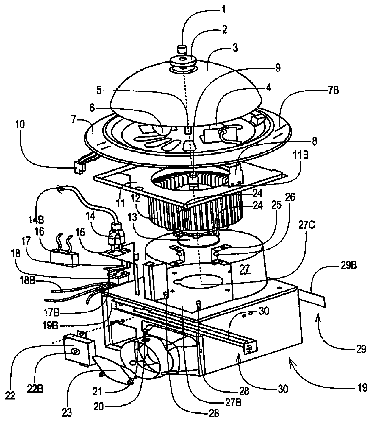
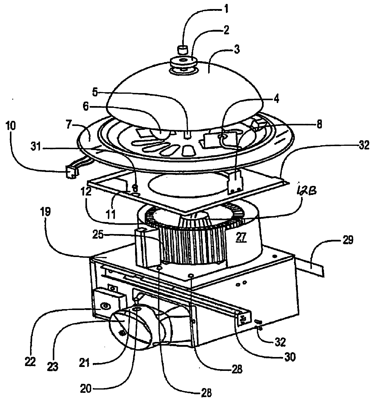
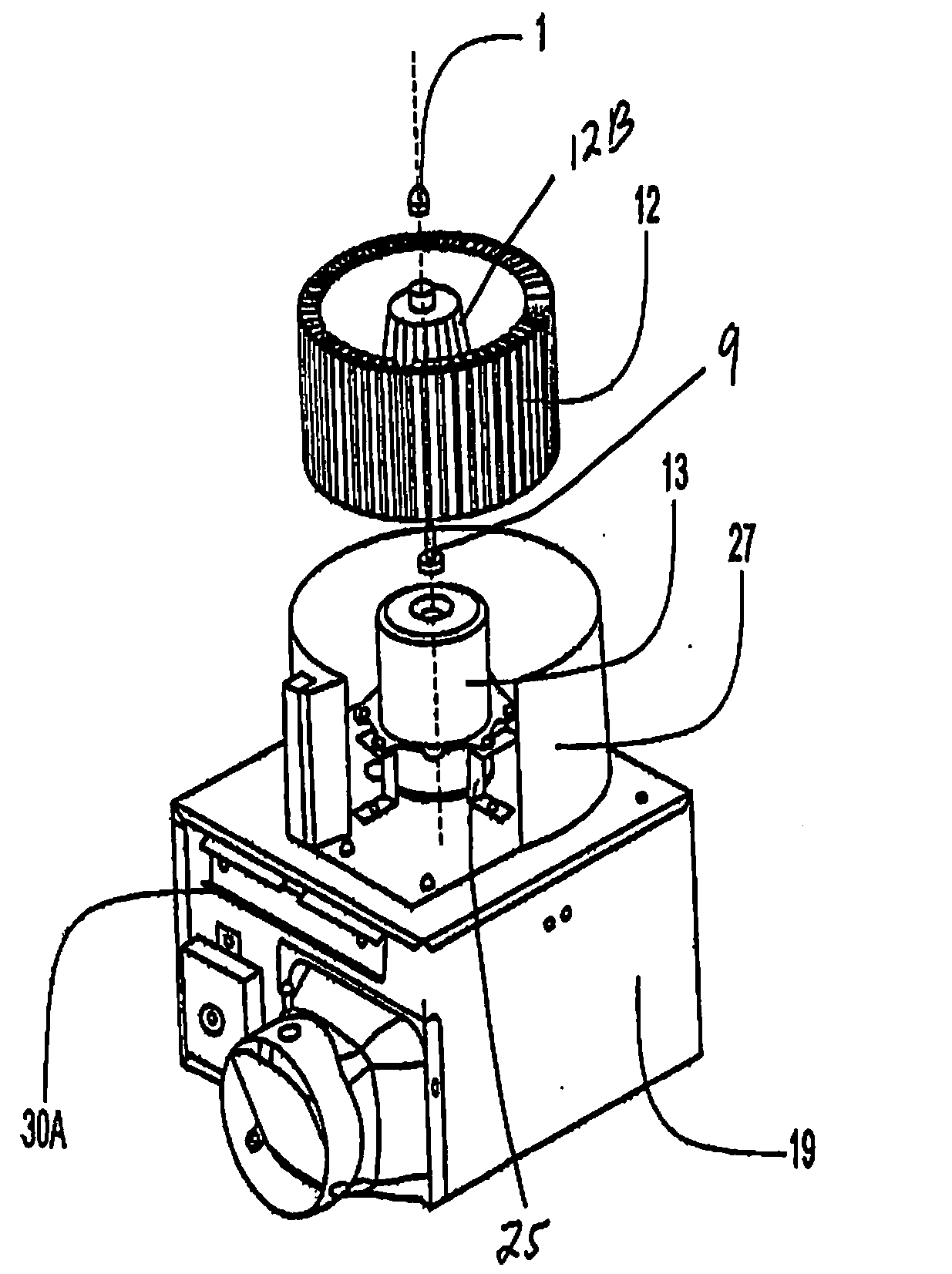
[0038]A list of the components for FIGS. 1-11 will now be described.[0039]1. Decorative Nut.[0040]2. Decorative Cover.[0041]3. Glass Shade / Light[0042]4. Socket(2)[0043]5. Connect Screw[0044]6. Bulb(2)[0045]7. Grille Rim[0046]7B. slotted openings[0047]8. Grill bracket[0048]8B. Flange edges[0049]9. M8 Tower Form[0050]10. Plug 3-Pin[0051]11. Cover Plate[0052]11B. Central opening[0053]12. Impeller(Blower wheel)[0054]13. Electric Motor[0055]14. Plug 2-Pin[0056]14B. wire lea...


PUM


Abstract

Apparatus, systems and methods of generating 70 (seventy) CFM (cubic feet per minute) from ventilation fans for bathrooms with flush mount lights and having the motor partially inside and beneath the blower wheel. A one piece or multipiece housing for the bath fan can be attached to joists in the ceiling by a long telescoping mounting bracket, and a short telescoping mounting bracket that are each directly mounted on opposite outer side walls of the housing. A decorative pan about the light can have vents that receive the incoming air into the fan, which is exhausted therefrom by the motor driven blower.

Description

[0001]This application is a Continuation patent application of U.S. patent application Ser. No. 13 / 042,992 filed Mar. 8, 2011, now U.S. Pat. No. 9,175,874, which claims the benefit of priority to U.S. Provisional Patent Application Ser. No. 61 / 381,605 filed Sep. 10, 2010. The entire disclosure of each of the applications listed in this paragraph are incorporated herein by specific reference thereto.FIELD OF USE[0002]This invention relates to ventilation exhaust fans, and in particular to apparatus, devices, systems and methods of 70 CFM ventilation fans for bathrooms with flush mount lights and having the motor underneath the blower wheel.BACKGROUND AND PRIOR ART[0003]Various types of bathroom ventilation fans have been proposed and used over the years. See for example, U.S. Pat. No. 4,867,640 to Penlesky et al.; U.S. Pat. No. 4,510,851 to Sarnosky et al.; U.S. Pat. No. 6,261,175 to Larson et al.; U.S. Pat. No. 6,488,579 to Larson et al.; U.S. Pat. No. 6,802,770 to Larson et al.; U....

Claims


Application Information

Patent Timeline
Patent Type & Authority Applications(United States)
IPC IPC(8): F24F7/007F04D19/00
CPCF04D19/00F24F7/007F21V33/0088F21V33/0096F21Y2113/00F24F13/06F24F13/078
Inventor TOM, LAWRENCE
Owner CHIEN LUEN INDS
Why Eureka
Try Eureka