Eureka AIR delivers breakthrough ideas for toughest innovation challenges, trusted by R&D personnel around the world.

Method for Selective Oxide Removal

Active Publication Date: 2016-02-18
INTERUNIVERSITAIR MICRO ELECTRONICS CENT (IMEC VZW)
View PDF5 Cites 3 Cited by
  • Summary
  • Abstract
  • Description
  • Claims
  • Application Information

AI Technical Summary

Benefits of technology

The invention provides a method for protecting a material during etching without the need for depositing additional layers. The method uses an ion beam or neutral beam reactor that has no self-bias voltage, which allows for better control of ion energies and reduces sputtering or loss of material during selective oxide etching. The invention also preserves the thickness of the material after etching is completed.

Problems solved by technology

However, such a high consumption of silicon nitride cannot be tolerated for contact etching, where the nitride of the sidewalls spacer and / or gate cap is deemed to be consumed, especially in the processing of advanced technology nodes.
Such a consumption of the nitride of the sidewalls spacer and / or nitride cap leads exposure of the gate electrode resulting in an electrical shorting of the gate electrode with the source or the drain region after establishing the electrical contact.
This means that such a bread-loafed profile poses the risk of having merged corners, thus jeopardizing or putting extra undesired challenges to the contact etch process.

Method used


Image

  • Method for Selective Oxide Removal
  • Method for Selective Oxide Removal
  • Method for Selective Oxide Removal

Examples


Embodiment Construction

[0043]The present invention will be described with respect to particular embodiments and with reference to certain drawings, but the invention is not limited thereto but only by the claims. The drawings are only schematic and are non-limiting.

[0044]Reference throughout this specification to “one embodiment” or “an embodiment” means that a particular feature, structure or characteristic described in connection with the embodiment is included in at least one embodiment of the present invention. Thus, appearances of the phrases “in one embodiment” or “in an embodiment” in various places throughout this specification are not necessarily all referring to the same embodiment, but may. Furthermore, the particular features, structures or characteristics may be combined in any suitable manner, as would be apparent to one of ordinary skill in the art from this disclosure, in one or more embodiments.

[0045]Similarly it should be appreciated that in the description of exemplary embodiments of th...


PUM


Abstract

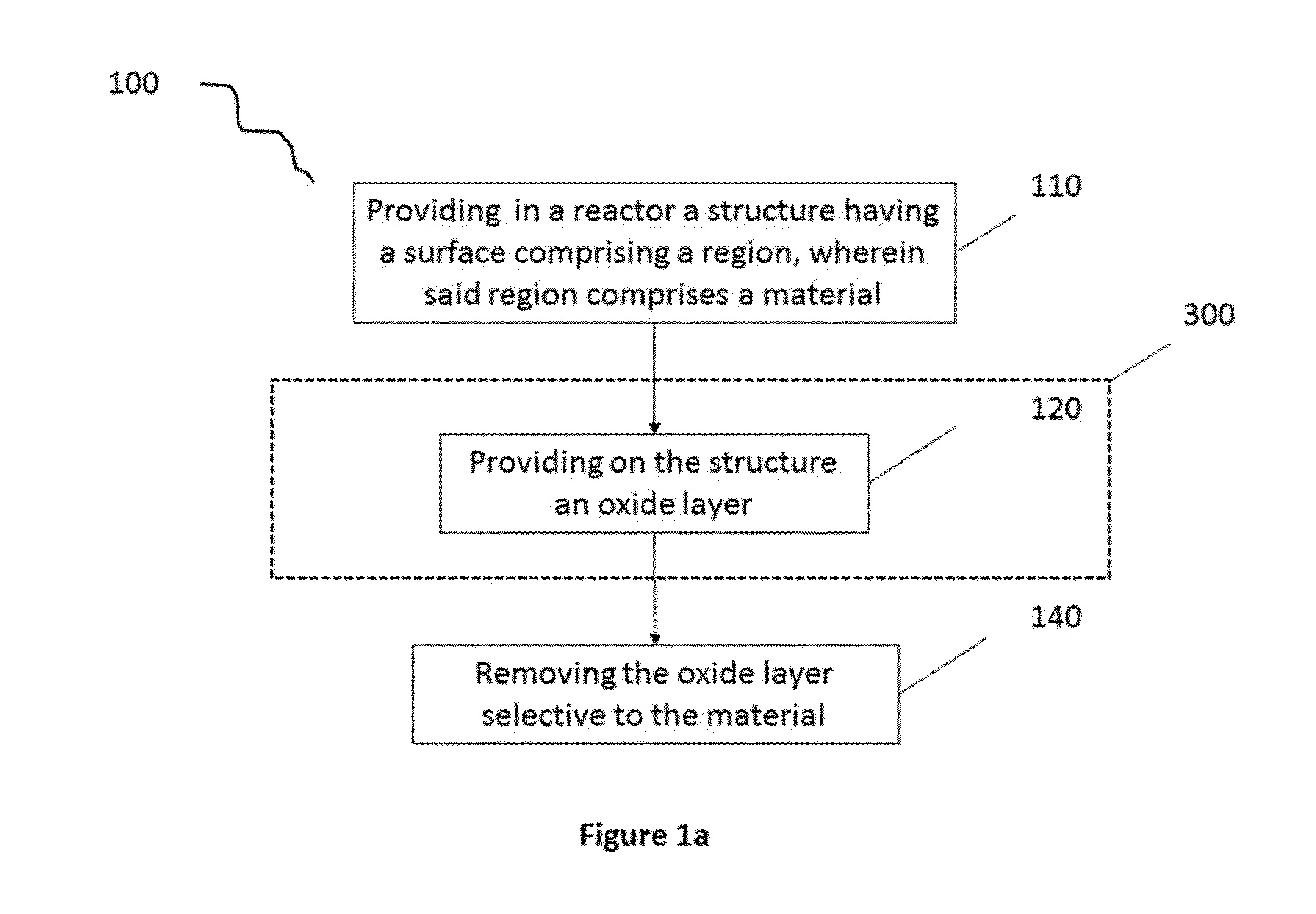
A method for removing oxide selective to a material comprising at least silicon and at least nitrogen is disclosed, the method comprising providing in a reactor a structure having a surface comprising a region, wherein said region comprises a material comprising at least silicon and at least nitrogen, providing on said structure an oxide layer overlying at least a part of said region, and removing said oxide layer selective to said material by etching, thereby exposing at least a part of said at least overlaid part of said region, wherein said etching is done only by providing an etchant gas comprising boron, whereby a voltage bias lower than 30 V is applied to the structure.

Description

CROSS-REFERENCE TO RELATED APPLICATIONS[0001]This application claims priority from EP 14181242.0, filed Aug. 18, 2014, and from EP 14190146.2, filed Oct. 23, 2014, which are incorporated by reference in its entirety.TECHNICAL FIELD OF THE INVENTION[0002]The present invention is related to the field of material removal. More specifically, it is related to a method for removing oxide on a structure selective to a material comprising at least silicon and at least nitrogen. The present invention also relates to removing oxide of a semiconductor structure selective to a material comprising at least silicon and at least nitrogen, in semiconductor processing.BACKGROUND OF THE INVENTION[0003]Selective material removal refers to being able to remove one material preferentially over another by means of a material removal technique when these materials are subjected to the same material removing environment. Even though there are various material removal techniques, etching is one of the most ...

Claims


Application Information

Patent Timeline
IPC IPC(8): H01L21/311C01B35/06C09K13/00
CPCH01L21/31144C09K13/00C01B35/061H01L21/31116H01L21/76897
Inventor KUNNEN, EDDYPARASCHIV, VASILE
Owner INTERUNIVERSITAIR MICRO ELECTRONICS CENT (IMEC VZW)
Why Eureka
Eureka Blog
Learn More