
HYPERFINE INTERPOLATED RANGE FINDING FOR CW LIDAR, RADAR, and SONAR USING REPEATING WAVEFORMS AND FOURIER TRANSFORM REORDERING

a hyperfine interpolation and range finding technology, applied in wave based measurement systems, instruments, using reradiation, etc., can solve the problems of limiting the sample rate, limiting the current type of interpolation, and limiting the data resolution, so as to enhance the apparent sample rate of data collection, enhance data resolution, and enhance the effect of data resolution

Inactive Publication Date: 2016-02-18
NASA
View PDF5 Cites 15 Cited by
  • Summary
  • Abstract
  • Description
  • Claims
  • Application Information

AI Technical Summary

Benefits of technology

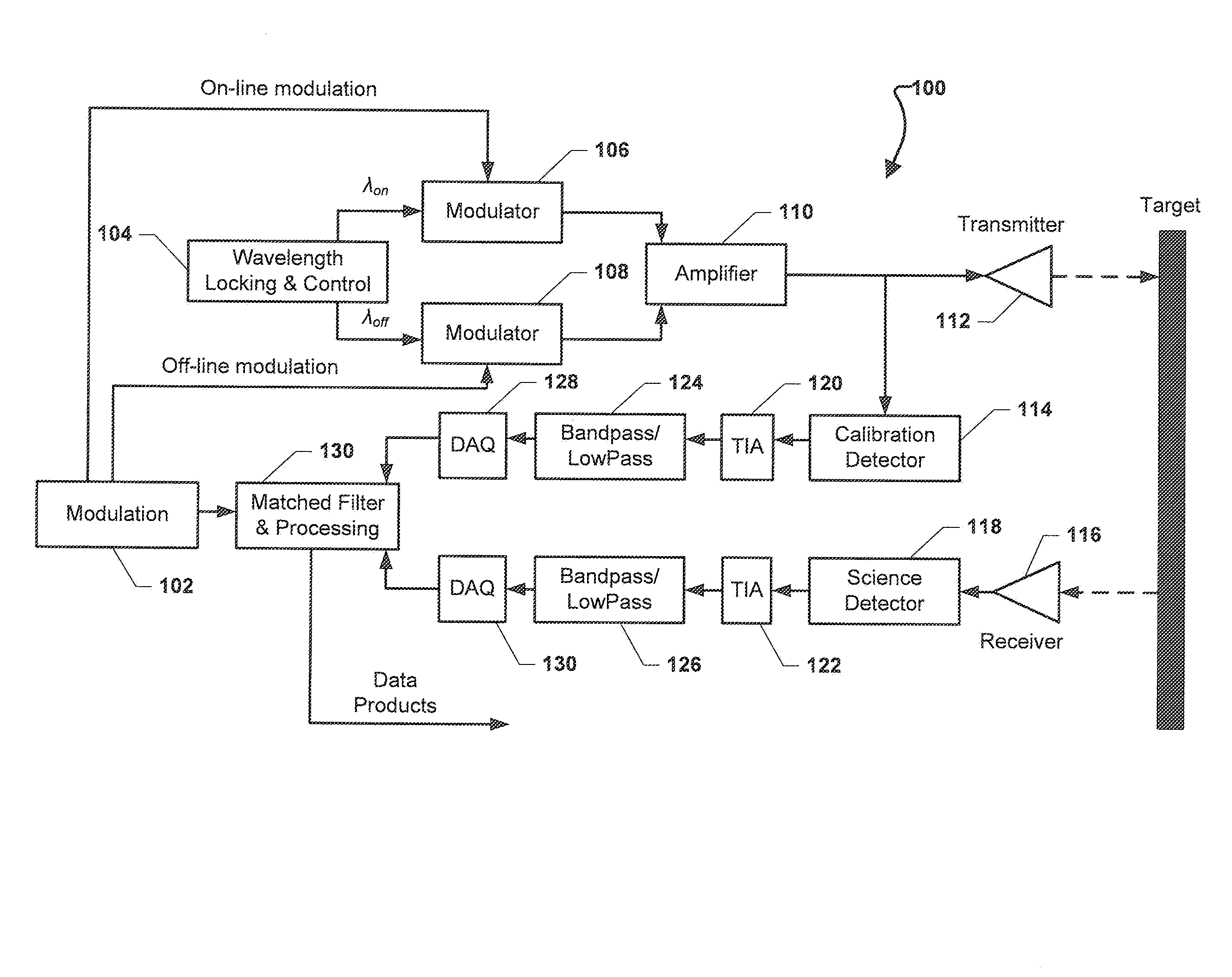
The present invention describes a way to improve the speed of collecting data from systems like CW Lidar, Radar, or Sonar that use a repeating waveform. This is achieved by reordering the data in the frequency domain and enhancing the apparent sample rate. This results in a highly interpolated range profile with improved data resolution. Additionally, a deconvolution algorithm like maximum entropy or Richardson-Lucy can further improve the resolution of the system. Overall, the invention enables real-time finer range measurements from these systems.

Problems solved by technology

Limitations in the hardware of the some conventional CW Lidar, Radar, or Sonar systems may limit the sampling rate, and therefore the data resolution may also be limited.
For example, hardware limitations may limit the sample rate such that only a 75 meter data resolution may be achieved.
Various current types of interpolation can be applied to the data from conventional CW Lidar, Radar, or Sonar systems, but current types of interpolation can take too long and can require too many resources to be implemented in a real time application.

Method used


Image

  • HYPERFINE INTERPOLATED RANGE FINDING FOR CW LIDAR, RADAR, and SONAR USING REPEATING WAVEFORMS AND FOURIER TRANSFORM REORDERING
  • HYPERFINE INTERPOLATED RANGE FINDING FOR CW LIDAR, RADAR, and SONAR USING REPEATING WAVEFORMS AND FOURIER TRANSFORM REORDERING
  • HYPERFINE INTERPOLATED RANGE FINDING FOR CW LIDAR, RADAR, and SONAR USING REPEATING WAVEFORMS AND FOURIER TRANSFORM REORDERING

Examples


Embodiment Construction

[0026]For purposes of description herein, it is to be understood that the specific devices and processes illustrated in the attached drawings, and described in the following specification, are simply exemplary embodiments of the inventive concepts defined in the appended claims. Hence, specific dimensions and other physical characteristics relating to the embodiments disclosed herein are not to be considered as limiting, unless the claims expressly state otherwise.

[0027]The word “exemplary” is used herein to mean “serving as an example, instance, or illustration.” Any implementation described herein as “exemplary” is not necessarily to be construed as preferred or advantageous over other implementations.

[0028]The various embodiments will be described in detail with reference to the accompanying drawings. Wherever possible, the same reference numbers will be used throughout the drawings to refer to the same or like parts. References made to particular examples and implementations are...


PUM


Abstract

Systems, methods, and devices may enhance the apparent sample rate of data collected using Nyquist sampling from a system, such as Continuous Wave (CW) Light detection and ranging (“Lidar”), Radio detection and ranging (“Radar”), or Sound Navigation and Ranging (“Sonar”), that has been modulated with a repeating waveform, such as linear swept frequency, by reordering of the data in the frequency domain. The enhancement of the apparent sample rate may result in a highly interpolated range profile where the data resolution may be enhanced by a factor equal to the number of repeats in the signal being processed, and may result in a highly detained range measurement with a high precision. The various embodiments may combine data from multiple modulation repeats into a single highly interpolated pulse, which may result in a real-time finer range measurement from CW Lidar, Radar, or Sonar systems.

Description

CROSS-REFERENCE TO RELATED PATENT APPLICATIONS[0001]This patent application claims the benefit of and priority to U.S. Provisional Patent Application No. 62 / 037,662, filed on Aug. 15, 2014, and U.S. Provisional Patent Application No. 62 / 064,492, filed on Oct. 16, 2014. The entire contents of the foregoing are hereby incorporated by reference in their entirety.STATEMENT REGARDING FEDERALLY SPONSORED RESEARCH OR DEVELOPMENT[0002]The invention described herein was made by employees of the United States Government and may be manufactured and used by or for the Government of the United States of America for governmental purposes without the payment of any royalties thereon or therefore.BACKGROUND OF THE INVENTION[0003]Continuous Wave (“CW”) Light detection and ranging (“Lidar”) is a sensing technology using light waves to determine a distance to objects. Radio detection and ranging (“Radar”) is a sensing technology using radio waves to determine a distance to objects. Sound Navigation an...

Claims


Application Information

Patent Timeline
Patent Type & Authority Applications(United States)
IPC IPC(8): G01S7/00G01S17/32G01S7/4865G01S7/4915
CPCG01S7/003G01S7/4865G01S7/4915G01S7/534G01S17/32G01S7/356G01S7/352
Inventor CAMPBELL, JOEL F.LIN, BINGNEHRIR, AMIN R.
Owner NASA
Learn More