
Method and Apparatus for Precise Temperature Brightness Compensation of LED

a temperature brightness compensation and led technology, applied in the direction of electric variable regulation, process and machine control, instruments, etc., can solve the problems of reducing reliability, limiting the use of led in some applications, and adding external sensors and components, etc., to achieve the effect of simple design

Active Publication Date: 2016-02-11
EDEN SVETLANA
View PDF3 Cites 16 Cited by
  • Summary
  • Abstract
  • Description
  • Claims
  • Application Information

AI Technical Summary

Benefits of technology

The present invention is about compensating for changes in temperature in LED lights. It offers a way to choose the parameters for a power supply that can achieve accurate brightness compensation at specific temperatures. The patent describes circuits that implemented this method and provides evidence of its effectiveness. Additionally, the patent explains how some circuits limit the current or shut down in case of an overcurrent. Overall, this technology ensures LED lights remain bright at different temperatures.

Problems solved by technology

This imperfection limits the use of LED in some areas of applications.
Additionally, the added external sensors and components reduce reliability and increases the costs of illuminators.
The necessity of an external temperature sensor is a significant limitation in use of LED drivers.
The prior-described prior art has difficulties.

Method used


Image

  • Method and Apparatus for Precise Temperature Brightness Compensation of LED
  • Method and Apparatus for Precise Temperature Brightness Compensation of LED
  • Method and Apparatus for Precise Temperature Brightness Compensation of LED

Examples


example 1

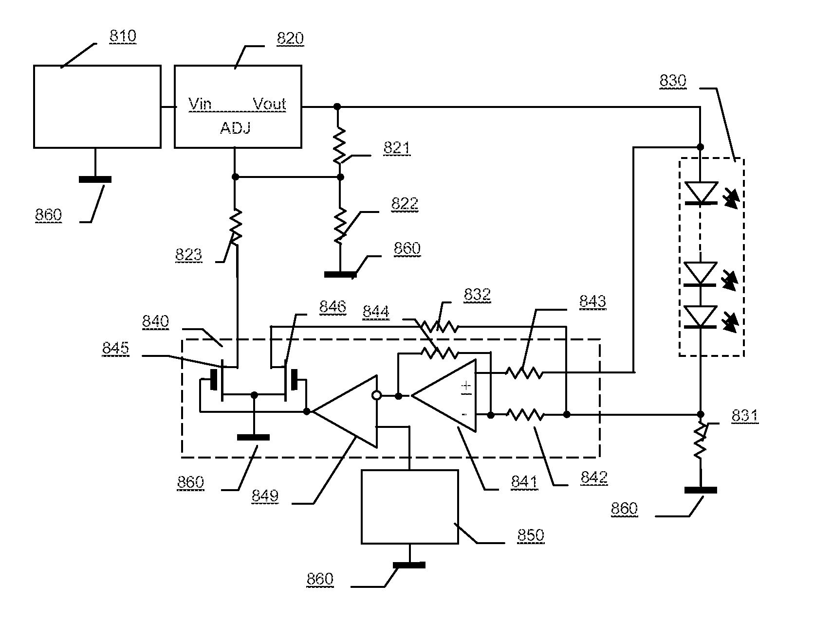
[0059]The experiment was conducted by the instrumentality measuring the system shown on FIG. 1A for temperature range from 0° C. to +40° C. with intervals of 5° C. This experimental data is presented in the Table 1. First, the brightness of LED type TLCY5100 was measured at temperature 20° C. and current 17 ma. This brightness value was taken as a reference and was used to compute relative brightness by dividing the brightness of the LED by the reference brightness. Next, relative brightness was measured in the specified temperature range using two power sources: a current power supply, and the aforesaid optimal supply. The data of the relative brightness of the LED with supply by current source 17 ma is presented in the second row of Table 1. This data show that in the temperature range from 0° C. to +40° C., the relative brightness of the LED varies in the range of ±20%. The data of relative brightness of the LED with supply by the optimal voltage source 2.16 V and through the opt...

example 2

[0063]The Experiment was Conducted by the instrumentality measuring the system shown on FIG. 1A for temperature range from 0° C. to +40° C. with intervals of 5° C. This experimental data is presented in the Table 2. First, the brightness of LED type HB5-439AWD was measured at temperature 20° C. and current 17 ma. This brightness value was taken as a reference and was used to compute relative brightness by dividing the brightness of the LED by the reference brightness. Next, relative brightness was measured in the specified temperature range using two power sources: a current power supply, and the aforesaid optimal supply. The data of the relative brightness of the LED with supply by current source 17 ma is presented in the second row of Table 2. This data show that in the temperature range from 0° C. to +40° C., the relative brightness of the LED varies in the range of ±8%. The data of relative brightness of the LED with supply by the optimal voltage source 3.51 V and through the op...


PUM


Abstract

The invention is a method and apparatus to provide a temperature compensation for LED brightness utilizing temperature dependence of voltage-current characteristic of the LED. Methods ensure the precise compensation of brightness of LED using two or more temperatures to tune an LED driver circuit without the use of thermistors or other temperature sensor.This method also allows for circuits that compensate brightness not only of a single LED but of an assembly of LEDs. The method allows to manufacture LED modules with built-in temperature brightness compensation circuit. These modules can be used in a variety of illuminating equipment including but not limited to home lights, vehicle turn or brake signals, traffic lights, and a backlight for LCD display.

Description

TECHNICAL FIELD OF THE INVENTION[0001]The present invention relates to lighting control systems for Light Emitting Diode (LED) equipment, notably temperature brightness compensation of LED for lighting systems.BACKGROUND OF THE INVENTION[0002]Light-emitting diodes (LED) lighting has become increasingly more popular in recent years. As a source of light, LED has many advantages over incandescent lighting, including high efficiency, reliability, and long life. However, the brightness of LED depends on temperature P-N junction and ambient temperature fluctuations. This imperfection limits the use of LED in some areas of applications.[0003]There are many patents which describe methods to address LED brightness, attempting to correct operating conditions to create stable lighting brightness. Most of these methods use external temperature sensors, such as PTC and NTC thermo-resistors, semiconductor diodes, and transistors of various sorts.[0004]All circuits that use external temperature s...

Claims


Application Information

Patent Timeline
Patent Type & Authority Applications(United States)
IPC IPC(8): H05B44/00H05B45/50
CPCH05B33/0815H05B33/0851H05B45/10H05B45/50H05B47/105H05B45/397Y02B20/30H05B45/14
Inventor ROBERT, KASIMOV
Owner EDEN SVETLANA
Learn More