
Patient transfer apparatus using side protector

a technology of patient transfer and side protector, which is applied in the field of patient transfer apparatus using side protector, can solve the problems of difficult to move the top movable board, difficult to apply patents, and expensive facilities, and achieve the effects of minimizing inconvenience, facilitating patient movement, and reducing the number of peopl

Active Publication Date: 2016-05-31
JEI YANGGYU
View PDF26 Cites 4 Cited by
  • Summary
  • Abstract
  • Description
  • Claims
  • Application Information

AI Technical Summary

Benefits of technology

The apparatus simplifies patient transfer by reducing the need for external power and separate devices, minimizing inconvenience and effort, especially for obese patients, allowing easier movement between beds and medical equipment with fewer personnel.

Problems solved by technology

Many filed and registered domestic and foreign patents use very complex devices or power-transmitting devices and thus a using procedure is complex and expensive facilities are required, so that the patents are not easy to practically apply.
U.S. Pat. No. 4,259,756 and KR 10-2002-0049632 etc. are relatively simple in structure and convenient in installation and operation, but suffer from a disadvantage that when the patient lies on a top movable board of the patient transfer apparatus, a great frictional force occurs between the top movable board and a mattress of the patient bed due to the weight of the patient and thus the top movable board is difficult to easily move.
However, a complex step is required of separately installing and withdrawing the transfer arms.
At this time, a distance over which the top movable board is moved over the patient bed has to be longer than a distance over which the patient's body on the top movable board is moved; rather, the distance over which the patient's body on the top movable board is moved is two times the distance over which the top movable board is moved over the patient bed; therefore, practical application is difficult.

Method used


Image

  • Patient transfer apparatus using side protector
  • Patient transfer apparatus using side protector
  • Patient transfer apparatus using side protector

Examples


Embodiment Construction

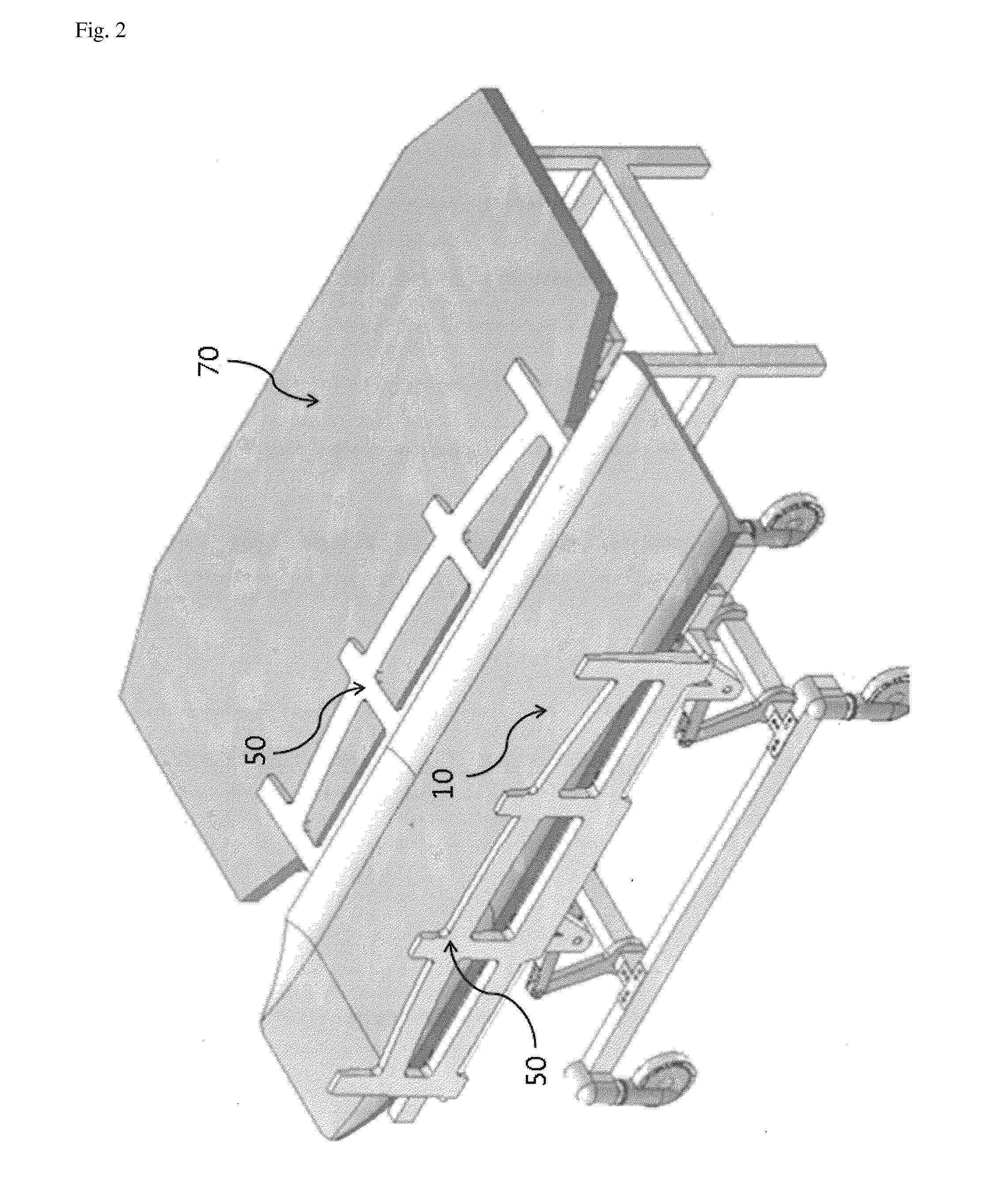
[0023]As shown in FIGS. 1 to 6, transfer arms (30) each equipped with transfer arm rollers (31) and transfer arm housings (34) are installed under a top movable board (10) of a patient-moving bed so that the top movable board can be easily moved over a patient bed. The transfer arm housings (34) are fixed to a frame (60) of the patient-moving bed. When the top movable board (10) of the patient-moving bed is moved over a mattress of the patient bed in order to load or unload the patient onto or from the top movable board (10), particularly in a case where the patient's body is loaded on the top movable board (10), it is not easy to move the top movable board over the patient mattress even though the rollers are equipped under the transfer arms (30). The applicant has been devised a wheeled chassis movable on the transfer arms (30) in order to overcome such a problem, as described in KR 10-2009-0053325.

[0024]A good method for easily moving the top movable board (10) over the patient b...


PUM


Abstract

A patient transfer apparatus includes a transfer arm for moving a top movable board on which the body of the patient is supported; a transfer arm housing fixed on a patient-moving bed frame so as to move the transfer arm; and a side protector laid on a patient bed so as to serve as a guide rail for enabling the transfer arm to easily move over the patient bed. The patient transfer apparatus enables the patient to simply lie on his / her side from a recumbent position such that the patient can be loaded or unloaded onto / from the patient-moving bed, thus minimizing inconveniences to the patient and easily moving the patient with fewer staff members.

Description

CROSS REFERENCE TO RELATED APPLICATIONS[0001]This application is a National Stage of International Application No. PCT / KR2013 / 004196 filed May 11, 2013, claiming priority based on Korean Patent Application No. 10-2012-0050558 filed May 12, 2012, the contents of all of which are incorporated herein by reference in their entirety.TECHNICAL FIELD[0002]An apparatus is required which can easily move a patient having problems with mobility while causing minimum inconvenience to the patient when the patient is transferred between a patient bed and a patient-moving bed. The present invention relates to an apparatus associated with a transfer of the patient occurring between the patient bed and the patient-moving bed or between the patient-moving bed (patient stretcher trolley) and various inspection devices when the patient is moved in a hospital.BACKGROUND ART[0003]Many patent applications are filed domestically and abroad which relate to a patient transfer apparatus for transferring a pat...

Claims


Application Information

Patent Timeline
Patent Type & Authority Patents(United States)
IPC IPC(8): A61G7/10A61G7/14A61G1/02A61G7/05
CPCA61G7/103A61G1/02A61G7/1036A61G7/1046A61G7/1057A61G7/1088A61G7/1034A61G2007/051A61G2007/0515A61G2200/16A61G7/051A61G7/0515A61G7/10
Inventor JEI, YANGGYU
Owner JEI YANGGYU
Learn More