Energy management system

a technology of energy management and energy management, applied in the direction of computer control, instrumentation, coupling device connection, etc., can solve the problems of inability to prevent users from wasting energy, no proactive energy saving schemes for users to save energy, and each of the above energy management devices has its weakness, so as to simplify the overall networking setup and minimize the chance of wi-fi blind spots. , the effect of reducing the chance of blind spots

Inactive Publication Date: 2016-02-11
KOOL KONCEPTS
View PDF45 Cites 52 Cited by
  • Summary
  • Abstract
  • Description
  • Claims
  • Application Information

AI Technical Summary

Benefits of technology

The invention is an energy management system that allows users to monitor and control the appliances in their system. The system detects the plugging and unplugging of appliances through a detection pin and notifies users through software or apps. The system also includes a detachable data transceiver device that can be easily recharged and used in different locations. The system can create a new Wi-Fi network or cover blind spots where computing devices are located. The server in the system holds several database systems and allows users to locate appliances in different premises across distances. The system is user-friendly and requires minimal effort to set up.

Problems solved by technology

Though some of the devices include the power measurement feature, there is usually no proactive energy saving schemes for users to save energy.
However, each of the above energy management devices has its weakness.
There is no idea which individual appliance consumes more.
This makes energy management difficult and inefficient.
The power measuring AC socket tells how much an appliance consumes, but will not proactively help the users about energy saving.
The only drawback is that the master and its peripherals have to be plugged on the same smart strip.
A campus wide energy management system is the most complete and automatic solution, but the implementation complexity, equipment cost, maintenance works will overwhelm the benefit of energy saved for a household user.

Method used


Image

  • Energy management system
  • Energy management system
  • Energy management system

Examples


Embodiment Construction

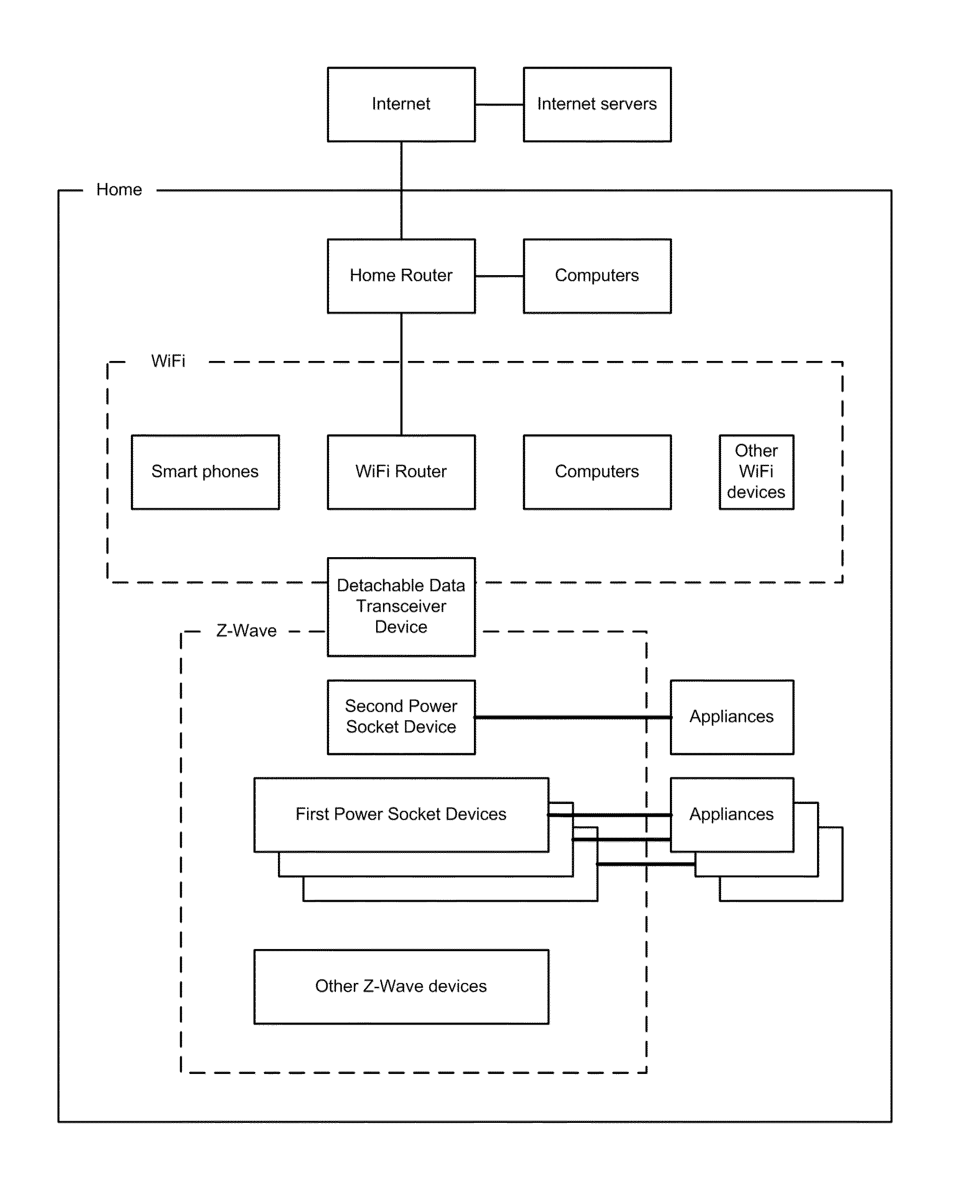
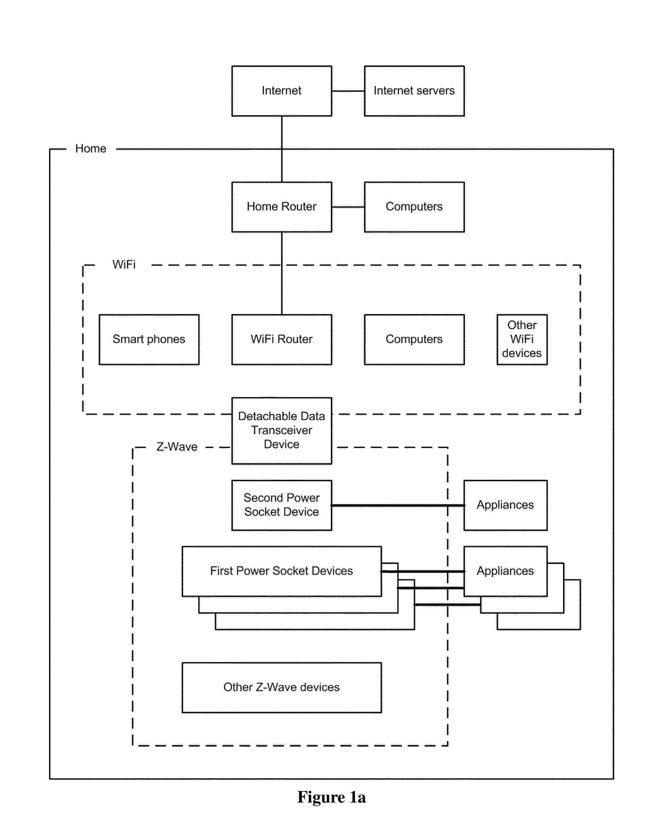
[0040]The present invention, the Energy Management System is a network system for household, offices or institutions, comprising a Detachable Data Transceiver Device together with a plurality of Power Measurement Devices.

[0041]The present invention provides a user-friendly energy management system which provides flexible functions, keep track of all energy consumption in the system and control of electrical appliances over a large range of distances. In one embodiment, said energy management system comprises: (a) a First Power Socket Device comprising (1) a plug, (2) one or more power measurement module, (3) one or more AC sockets each of which is coupled with an AC switch, (4) one or more communication modules, (5) a timing module, (6) a microcontroller, wherein said microcontroller controls the AC switches, and (7) a memory module, wherein said memory module stores control instructions for controlling the AC sockets; (b) a Second Power Socket Device comprising a plug, a docking sp...


PUM


Abstract

The present invention provides an Energy Management System which can be configured to automatically switch peripheral appliances on or off by detecting master appliances being in standby state, even though these appliances are located far away from each other in a premise, or even in other premises. The system is also capable of detecting whether the included appliances are plugged or unplugged to facilitate simple and efficient management of appliance power consumption for the sake of energy saving. In one embodiment, it also provides a detachable, battery-powered wireless sub-system, supporting dual operation modes, to improve wireless coverage of the system.

Description

FIELD OF THE INVENTION[0001]The present invention relates generally to systems for the automation of monitoring and controlling electrical appliances to reduce energy consumption and increase energy efficiency for households, offices and institutions.BACKGROUND OF THE INVENTION[0002]An energy management system can be a smart meter, a power measuring AC socket, a remote controlled AC socket, a smart power strip, a smart home system, or a campus wide energy management system through network control and monitoring.[0003]A smart meter is a household electricity meter which also has a communication sub-system to provide usage, instant or monthly, to the utility facility for billing and supply planning purposes. It creates a dynamic two-way dialogue between utilities and their customers. This dialogue aims to drive energy efficiency and demand response. Examples available on the market are TENDRIL. The electricity power consumption is a cumulated total per household.[0004]A power measurin...

Claims


Application Information

Patent Timeline
IPC IPC(8): G05F1/66G05B15/02
CPCG05B15/02G05F1/66G06F1/266H01R31/065G06F2200/261H01R13/665H01R13/70H01R25/003Y02D10/00
Inventor CHEN, ANDREW YUEN CHINCHENG, AMY DECEMTAM, TSZ KAI
Owner KOOL KONCEPTS
Why Eureka
Try Eureka