Projector

a projector and projector technology, applied in the field of projectors, can solve the problems of affecting image formation, inability to capture dust or any other object on the surface of the substrate, etc., and achieve the effect of suppressing the generation of moire patterns and reducing the visibility of the boundary

Inactive Publication Date: 2016-02-11
SEIKO EPSON CORP
View PDF4 Cites 0 Cited by
  • Summary
  • Abstract
  • Description
  • Claims
  • Application Information

AI Technical Summary

Benefits of technology

The invention relates to a projector with two spatial modulation devices arranged in series, where an aberration is used between the two devices to reduce the visibility of the boundary between bright and dark parts in the image. This results in a high-quality image with reduced generation of moire pattern. The relay system between the two pixel matrices generates aberrations instead of defocus to achieve a state where image is blurred even in a position where it should be in focus. The degree of blur can be controlled by adjusting the amount of aberration. The relay system can be designed to be symmetric or have a double Gauss lens or pair of meniscus lenses to further correct aberrations and improve telecentricity. The first and second pixel matrices can be transmissive liquid crystal pixel matrices to form a bright image.

Problems solved by technology

For example, in a state in which the surface of a substrate of a panel that forms one of the spatial modulation devices is brought into focus, dust or any other object present on the surface of the substrate is undesirably captured in an image even in the defocused state.
In general, the degree of a blur based on generation of an aberration varies depending, for example, on the field position, resulting in a uniform blur, which possibly affects image formation.

Method used


Image

  • Projector
  • Projector
  • Projector

Examples


first embodiment

[0026]A projector according to a first embodiment of the invention will be described below in detail with reference to the drawings.

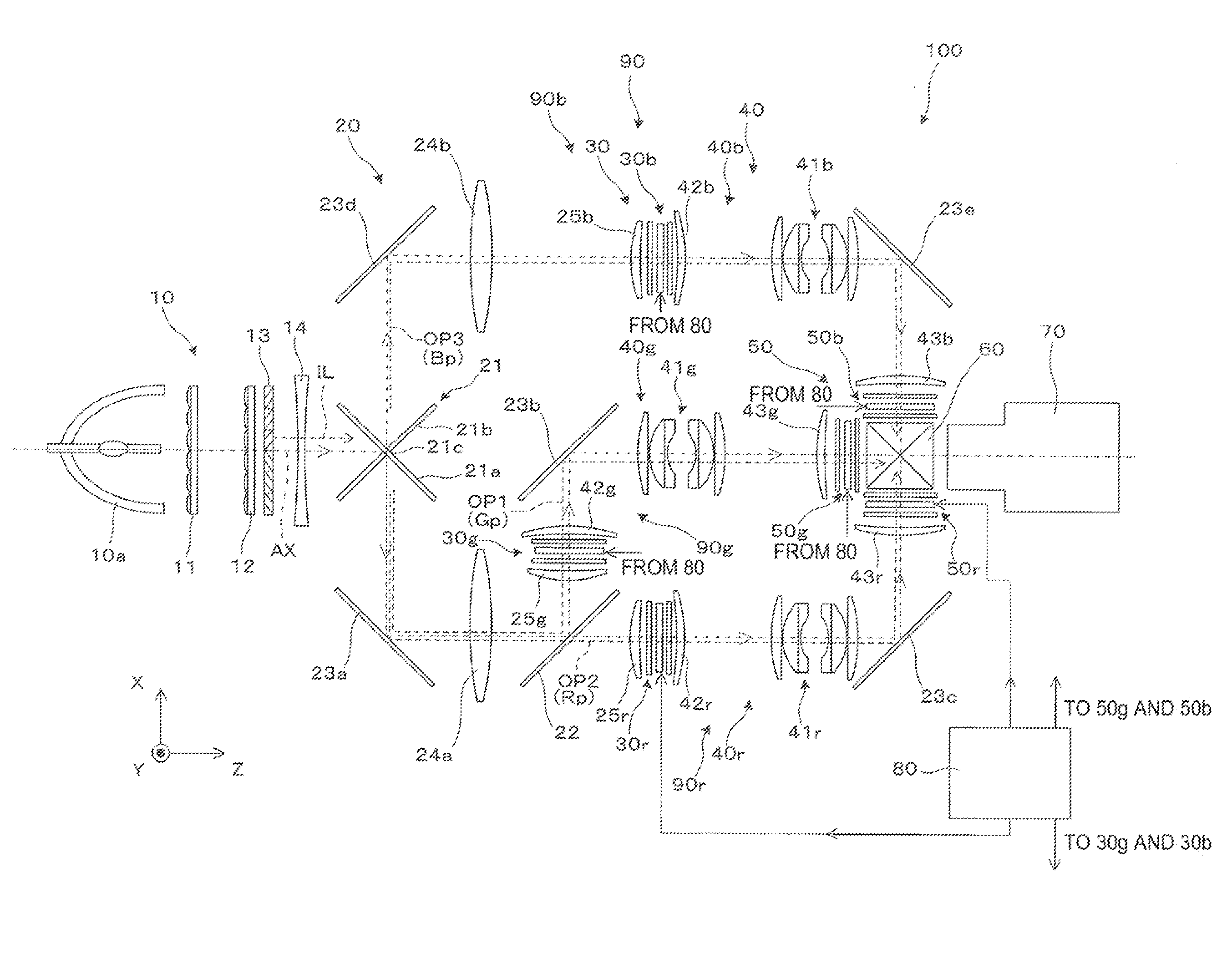
[0027]A projector 100 according to the first embodiment of the invention includes an illumination system 10, which outputs illumination light, a color separation / light guiding system 20, which separates the illumination light into color light fluxes and guides them, a modulation system 90, which spatially modulates the color light fluxes separated from the light outputted from the illumination system 10 by the color separation / light guiding system 20, a light combining system 60, which combines the separated, modulated color light fluxes (modulated light fluxes), a projection system 70, which projects the combined light, and a projector controller 80, as shown in FIG. 1. Among them, in particular, the modulation system 90 includes a light control system 30, which includes first pixel matrices, a relay system 40, which is responsible for relay of light f...

example 1

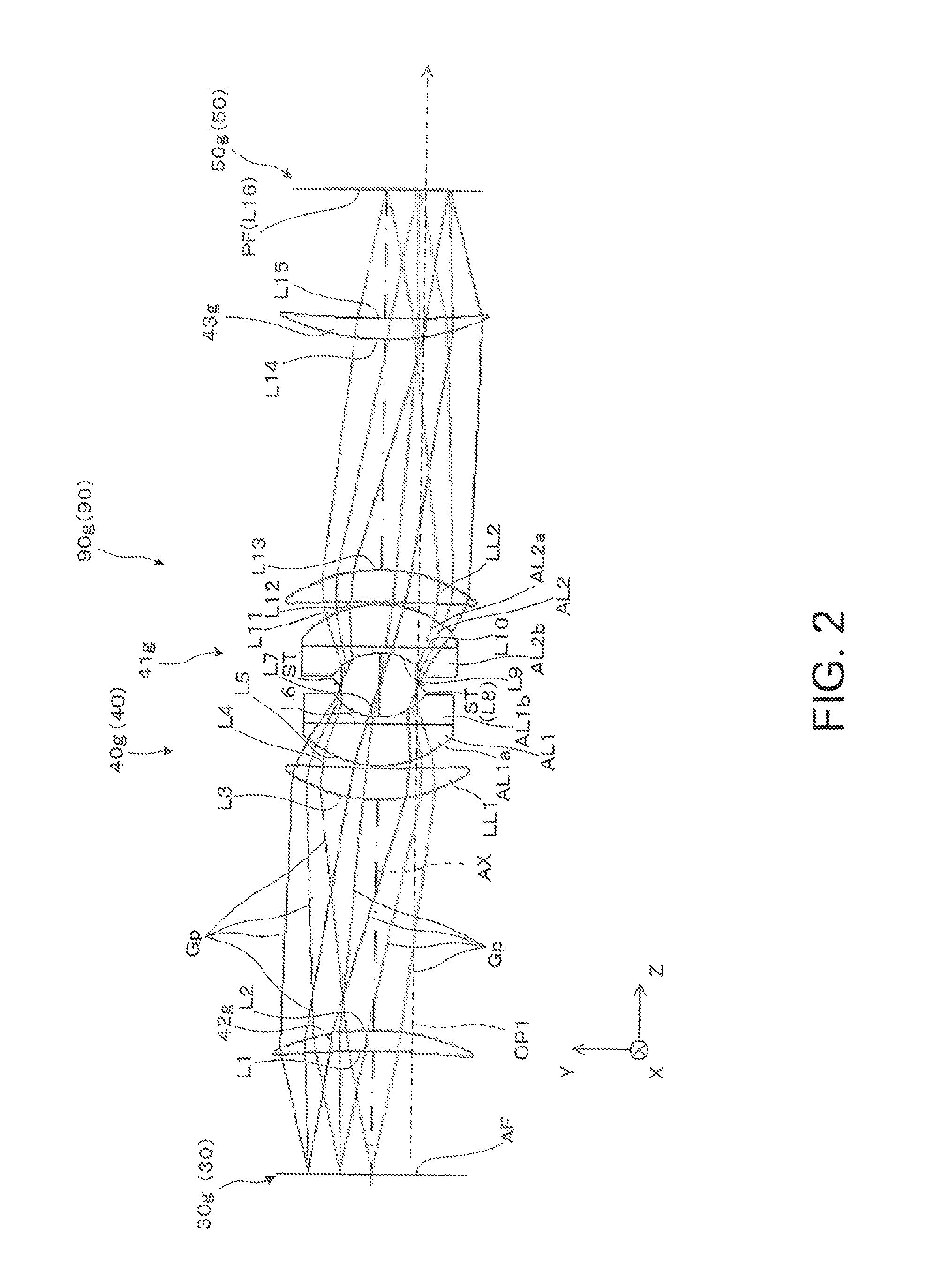
[0065]Table 1, which is presented below, shows data on the optical surfaces that forma relay system in Example 1. FIGS. 1 and 2 show the lenses in Example 1. In the upper field in Table 1, “surface number” represents numbers assigned to lens surfaces and other planes sequentially from the object side. That is, the surface numbers correspond to surfaces L1 to L16 shown in FIG. 2. Further, as a specific aspect of the projector including the relay system, it is, for example, conceivable that the pixel interval L is 100 μm, the relay system is an equal magnification optical system (M=1), and the value F of the f-number of the relay system is F=2.5.

TABLE 1SurfaceRadius ofInter-surfacenumbercurvature (R)distance (D)NdνdObject (AF)∞231−20041.8466623.82−46.344331.5461.8044039.64311.40.5520.3681.7995242.26∞1.21.7618226.5711.026.168 (aperture)∞6.169−11.021.21.7618226.510∞81.7995242.211−20.360.512−311.461.8044039.613−31.54441446.341.8466623.8152002316 (PF)∞2

[0066]The aberrations generated by t...


PUM


Abstract

A relay system (formed of a plurality of optical systems) that generates a spherical aberration allows each light ray flux to be so adjusted that the cross section thereof has a moderate size (moderate degree of spread) on an image panel surface of each color modulation light valve, that is, the light ray flux is not brought into complete focus but is blurred. Further, as the aberrations to be generated, the amount of spherical aberration is set to be much greater than those of the other third-order aberrations, whereby generated spots are allowed to have the same shape irrespective of the field position.

Description

BACKGROUND[0001]1. Technical Field[0002]The present invention relates to a projector including a first spatial modulation device and a second spatial modulation device arranged in series along an optical path.[0003]2. Related Art[0004]There is a known projector in which two spatial modulation devices are arranged in series for an increase in contrast of an image (see JP-A-2007-218946, for example). In this case, a relay lens is disposed between the two spatial modulation devices to superimpose an image of one of the two spatial modulation devices on the other spatial modulation device.[0005]In JP-A-2007-218946, in which two or more spatial modulation devices are arranged in series and a relay system achieves a substantial subject-image relationship between the two spatial modulation devices (the term “subject-image relationship” used herein means that one is imaged on the other and vice versa) to improve the contrast of an image, the relay system does not cause the position of an im...

Claims


Application Information

Patent Timeline
IPC IPC(8): G03B21/20
CPCG03B21/2053G03B21/005H04N9/3105H04N9/3126
Inventor OTANI, MAKOTOYAJIMA, AKITAKA
Owner SEIKO EPSON CORP
Why Eureka
Try Eureka