
Rapid Opening Gas Valve

a gas valve and rapid opening technology, applied in the field of valves, can solve the problems of limiting the speed with which the butterfly valve can be opened, and the design of conventional butterfly valves is not suitabl

Active Publication Date: 2016-02-11
GAITHER TOOL COMPANY
View PDF24 Cites 6 Cited by
  • Summary
  • Abstract
  • Description
  • Claims
  • Application Information

AI Technical Summary

Benefits of technology

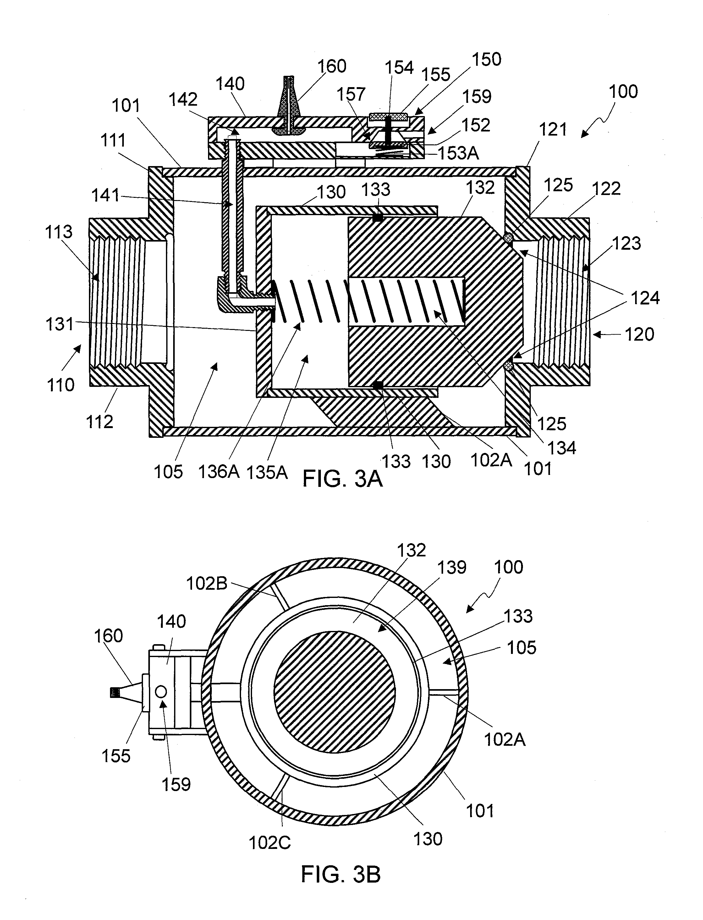
The patent describes a new design for a gas valve that allows for quick and easy release of pressurized gas. Unlike conventional valves, this design includes a control reservoir that allows for quick adjustment of the pressure to prevent the gas from flowing through the valve too quickly. The control reservoir is filled with pressurized gas to keep a piston in place and block the gas from escaping through the valve. The pressure in the control reservoir is adjusted to control the pressure at the valve. When the pressure in the control reservoir reaches the release pressure, the piston quickly moves to allow the gas to escape through the valve. This design provides a faster and more convenient way to control the release of gas from a valve.

Problems solved by technology

Valves designed to provide a fine control of gas flow are not suitable for such applications requiring a large burst of air.
However, the design of conventional butterfly valves suffers from limitation in the speed with which the butterfly valve can be opened, allowing the pressurized gas from a tank to escape.

Method used


Image

  • Rapid Opening Gas Valve
  • Rapid Opening Gas Valve
  • Rapid Opening Gas Valve

Examples


Embodiment Construction

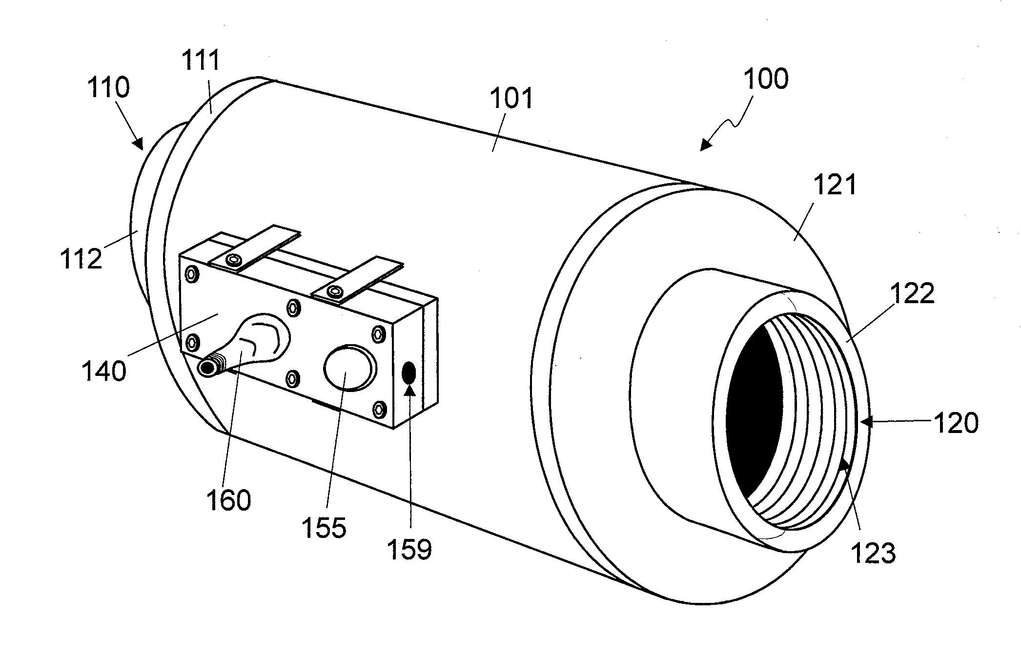
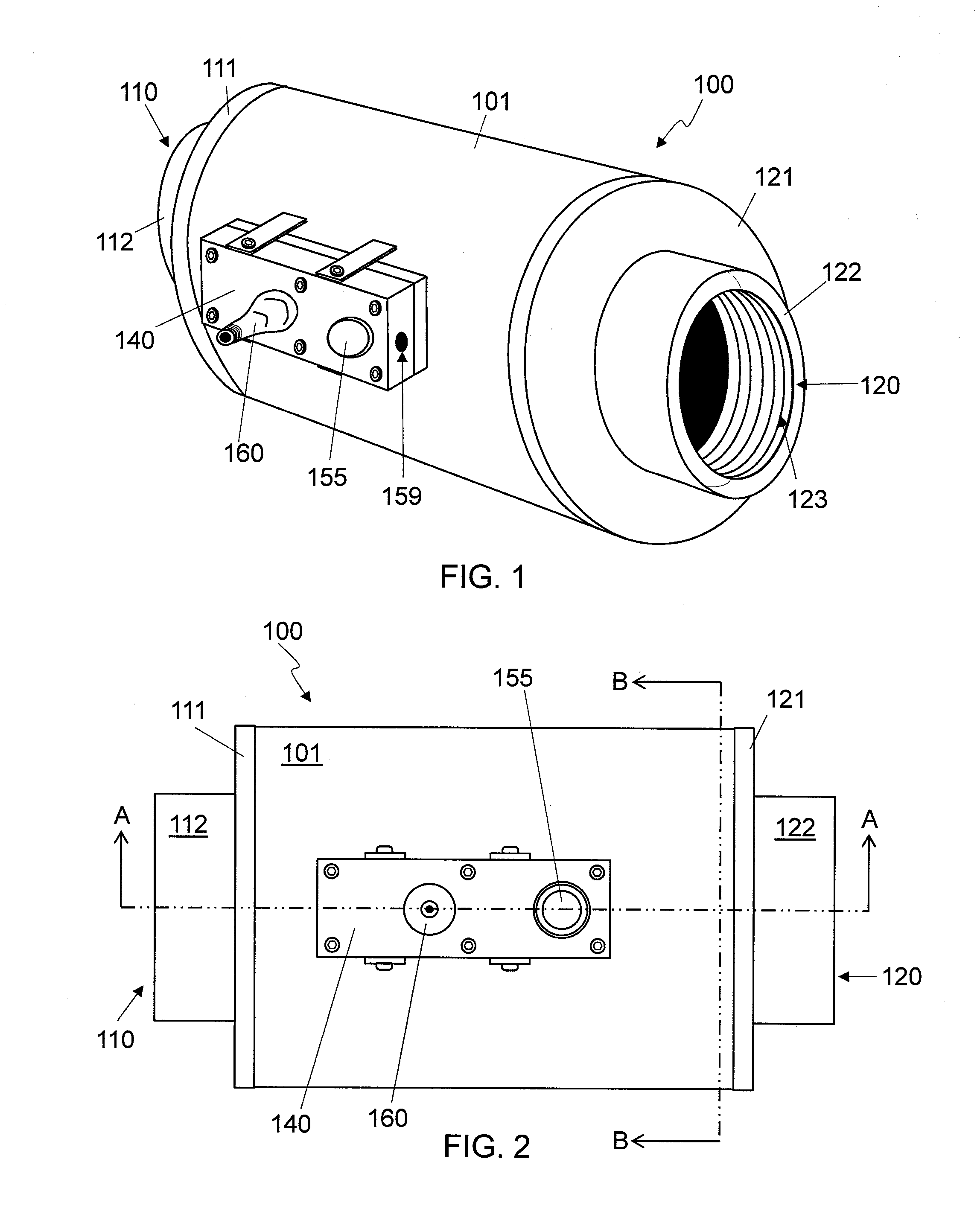
[0024]The present inventor recognized a problem with conventional design. Namely, the conventional designs of bead seating tools feature a tank size that is either too large (for sufficient air volume) or too heavily reinforced (for sufficient pressure) to be conveniently used in order to attain a burst of air sufficient to mount a tubeless tire on a wheel rim. The inventor recognized that by having a simple valve that could open more quickly than conventional ball valves or butterfly valves of conventional designs, a smaller, more easily portable tank might be used. The present invention provides a simple, low cost, pneumatically controlled, rapid-opening, gas valve that may be used for a bead seating tool or other applications. In this way, valves according to the various embodiments disclosed herein can be used with smaller, more easily portable, sized tanks.

[0025]In the following detailed description, numerous specific details are set forth by way of examples in order to provide...


PUM


Abstract

A pneumatically operated gas valve includes a piston positioned in a cylinder with one closed end so that the piston may seat against a gas outlet to close the gas valve. A control reservoir may be formed in the cylinder between the piston and the closed end of the cylinder. Means for filling the control reservoir with gas to a control pressure may be provided so that the control pressure acting against the piston may close the gas valve. A release valve may be opened to allow the gas in the control reservoir to escape through an exhaust port to open the gas valve.

Description

BACKGROUND[0001]1. Technical Field[0002]The present subject matter relates to valves. More specifically, the present subject matter relates to a pneumatically controlled, rapid-opening, gas valve.[0003]2. Description of Related Art[0004]Many types of valves suitable for controlling a flow of a gas are known in the art. Common types of gas valves mechanisms include ball valves, butterfly valves, and poppet valves. Gas valves may be actuated manually, electrically, or pneumatically. Some valves allow fine control of the flow of gas and others may simply have an open and a closed position. Some applications, such as for a bead seating tool used to seat a tubeless tire on a rim, require a rapidly opening valve to provide a burst of air. Valves designed to provide a fine control of gas flow are not suitable for such applications requiring a large burst of air.[0005]One conventional design for a rapidly opening gas valve is the butterfly valve. Conventional butterfly valves hold pressuriz...

Claims


Application Information

Patent Timeline
Patent Type & Authority Applications(United States)
IPC IPC(8): F16K24/04B60C29/06F16K1/36F16K15/20F16K31/122
CPCF16K24/04F16K1/36B60C29/06F16K31/1221F16K15/20B60C25/145F16K1/126Y10T137/0318B60C25/138
Inventor KUNAU, DANIEL
Owner GAITHER TOOL COMPANY
Learn More