
Lacrosse head pocket and related method of manufacture

a head pocket and head technology, applied in the field of lacrosse equipment, can solve the problems of requiring extensive maintenance, deteriorating performance, and a lot of lacrosse players, and achieve the effect of convenient manufacture, replacement and/or servi

Active Publication Date: 2016-02-11
WARRIOR SPORTS INC
View PDF5 Cites 0 Cited by
  • Summary
  • Abstract
  • Description
  • Claims
  • Application Information

AI Technical Summary

Benefits of technology

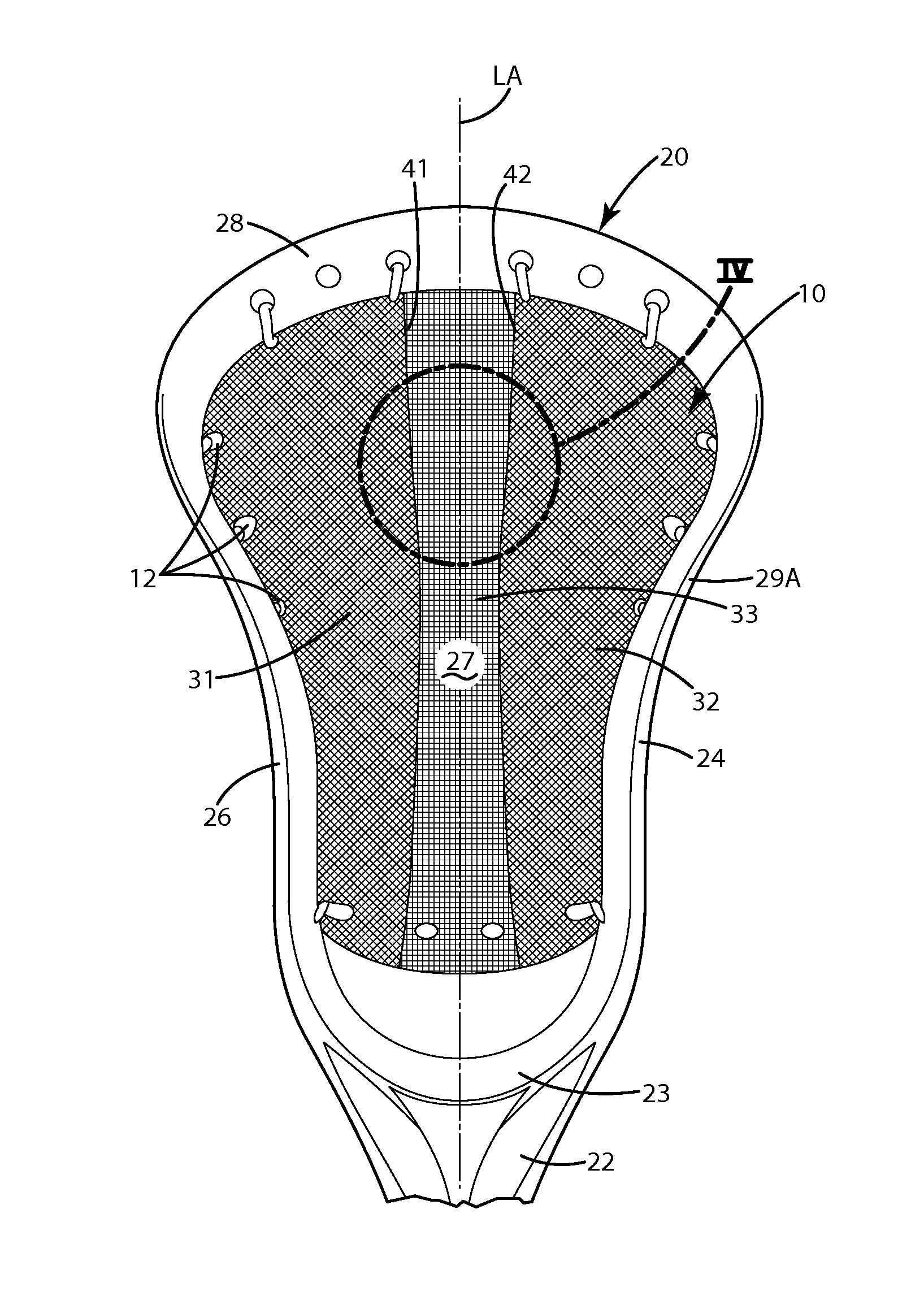
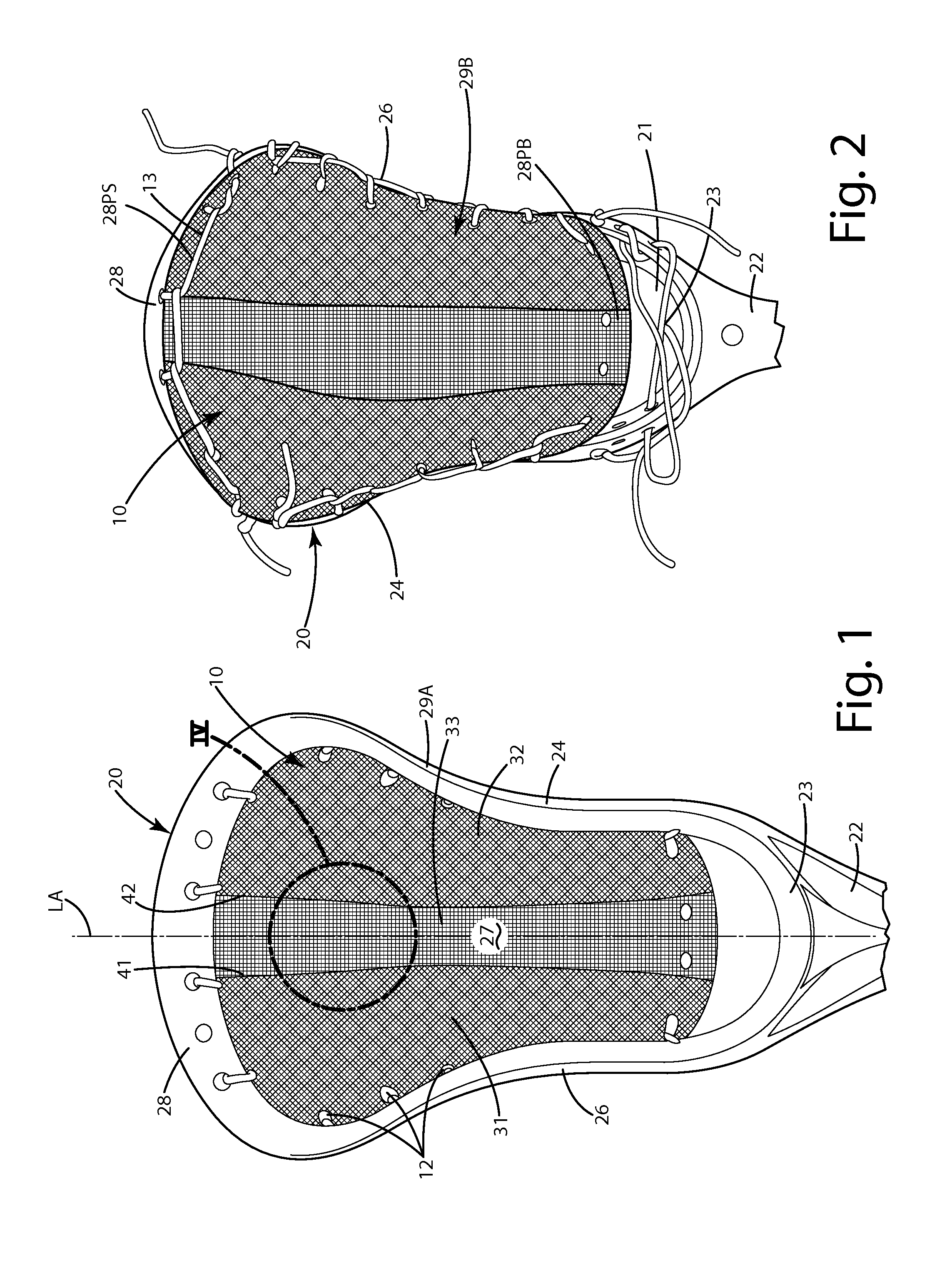
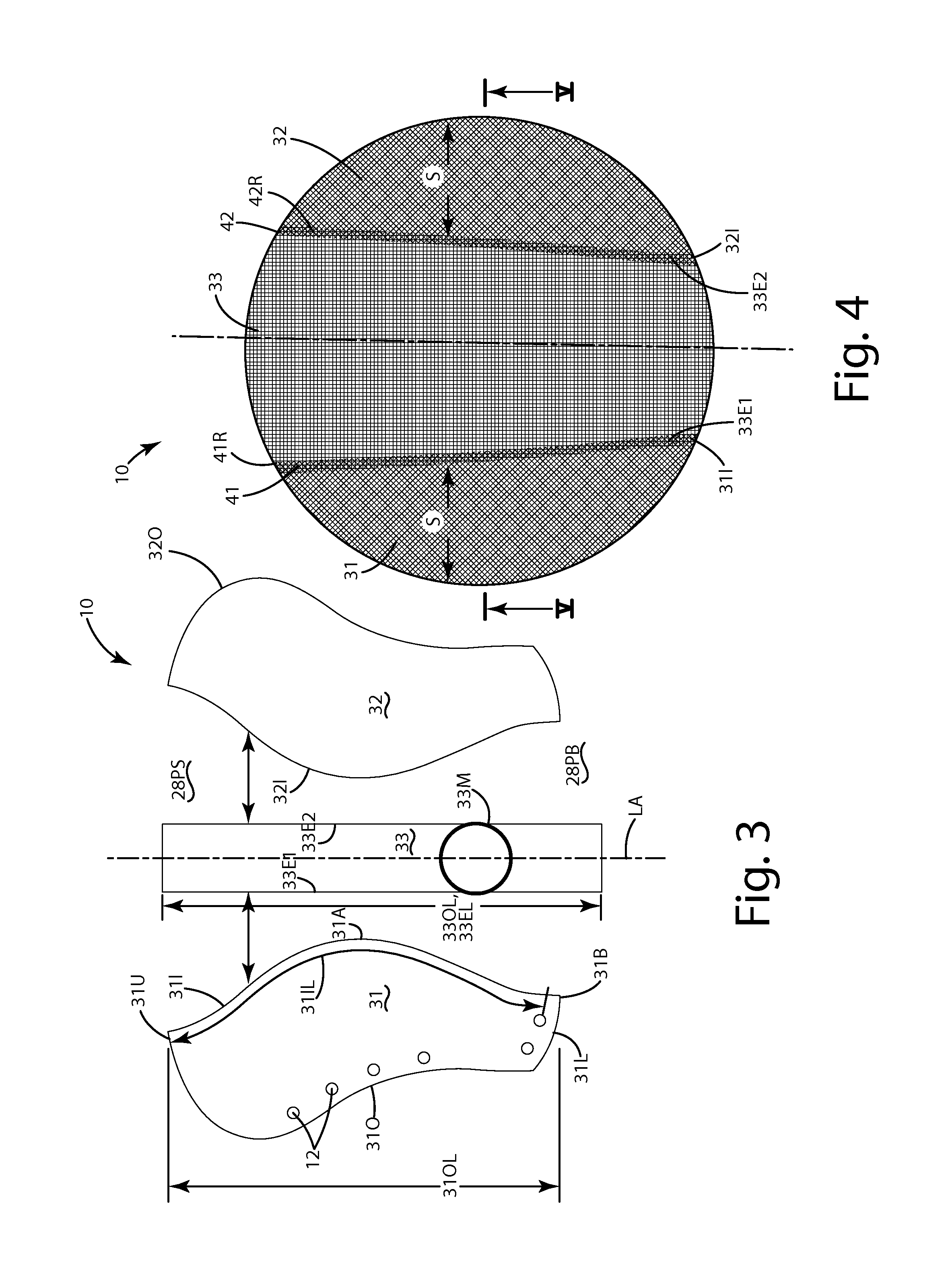
The patent describes a new lacrosse head with a durable and well-performing pocket. The pocket is easy to make, replace, and service. It can be made from a textile material with specific shapes and a flexible frame made of polymer. The flexible frame can be reinforced with runners and shooting elements. The pocket is not affected by weather changes and can be pre-assembled and installed on the lacrosse head with minimal break-in and skill. The pocket is consistent from one pocket to the next and can be repeatably customized. The methods described allow for precise replication of pockets and heads at a commercial level.

Problems solved by technology

Such traditional pockets typically require extensive maintenance, and are prone to deteriorated performance when the thongs are subject to moisture.
In addition, when a traditional pocket wears out, the mere thought of replacing it can be daunting to many, particularly younger or less experienced lacrosse players.
Users sometimes intertwine additional pieces of lace in the mesh to form the same, but this can require a special level of skill and time to do it properly.

Method used


Image

  • Lacrosse head pocket and related method of manufacture
  • Lacrosse head pocket and related method of manufacture
  • Lacrosse head pocket and related method of manufacture

Examples


first alternative embodiment

IV. First Alternative Embodiment

[0121]A first alternative embodiment of the lacrosse pocket is illustrated in FIG. 7 and generally designated 110. The pocket shown there is similar in structure, function and operation to the embodiment described above with several exceptions. For example, at the seams 141 and 142, where the seam-runners 141R and 142R are formed, the sections are joined with stitching. For example, first stitching 145 joins the edge 13I1 of the lateral pocket portion 131 and edge 133E of the middle pocket portion 133. The stitching 145 is sewn through the respective edges to join them with one another.

[0122]Second stitching 146 can be sewn through the edges 133E2 and 132I of the respective pocket sections to join those sections with one another. The stitching 145 and 146 can be in the form of one or more elongated strands of material, separate from the strands or material from which the respective sections 131, 132 and 133 are constructed. The stitching can be a cont...

second alternative embodiment

V. Second Alternative Embodiment

[0124]A second alternative embodiment of the lacrosse pocket as illustrated in FIG. 7A and generally designated 210. The pocket shown there is similar in structure, function and operation to the embodiments described above with several exceptions. For example, in this construction, rather than using a thermal bond or stitching, the edges of the different sections are joined with an adhesive. As shown, the inner edge 231I of the lateral section 231 is joined with the edge 233E1 of the middle pocket section 233 with an adhesive 245, which is illustrated in a finished, dried or cured state. The edges, as illustrated, are in close proximity with one another. Alternatively, they can be overlapped or abutted against one another depending on the particular application and the desired adhesive. The adhesive 246 can also join the edges 233E2 and 232I of the respective middle pocket section 233 and lateral pocket section 232.

[0125]The adhesives 245 and 246 can ...

third alternative embodiment

VI. Third Alternative Embodiment

[0127]A third alternative embodiment of the lacrosse pocket is illustrated in FIGS. 8-10 and generally designated 310. The pocket shown there is similar in structure, function and operation to the embodiments described above with several exceptions. For example, the pocket 310 can include fewer sections than the embodiments described above. As an example, the pocket can include only a first lateral section 331 and a second lateral section 332. These lateral sections are disposed on opposite sides of the longitudinal axis LA. These sections as shown in FIG. 9 can include the respective inner edges 331I and 332I similar to those described in connection with the embodiments above, these edges, however, rather than being joined with a middle section, can be joined directly with one another along the seam 341 as shown in FIG. 10. Where they are joined, the seam can be formed via a thermal bond, stitching, adhesive or other means described herein.

[0128]The ...


PUM

PropertyMeasurementUnit
thicknessaaaaaaaaaa
angleaaaaaaaaaa
diameteraaaaaaaaaa

Abstract

A lacrosse head pocket and a related method of manufacture are provided to facilitate consistent, repeatable and / or custom manufacture of lacrosse equipment. The pocket can be constructed from multiple different sections joined with one another, or can be knitted, weaved or otherwise assembled on an automated assembly machine from strands, and / or can be formed as a unitary textile material having regions / sections with different physical and / or mechanical properties. The pocket can be integrally molded within portions of a lacrosse head to eliminate manually constructed connections between the pocket and lacrosse head. The lacrosse head can be integrally molded with a lacrosse handle to provide a one-piece unitary lacrosse stick. Related methods of manufacturing also are provided.

Description

BACKGROUND OF THE INVENTION[0001]The present invention relates generally to lacrosse equipment, and more particularly, to a lacrosse head pocket and a related method of manufacture.[0002]Conventional lacrosse sticks include a head joined with a handle. The head includes a frame that forms a region within which a lacrosse ball can be caught, held or shot. A net is joined with the back side of the frame. Typically, the net is constructed from conventional, large diameter laces (e.g., a traditional pocket) or mesh (e.g., a mesh pocket), which is further connected to the frame via multiple small holes defined by the frame. The net forms a pocket within which the lacrosse ball is held while a player is in possession of the ball, and can be a determinant factor as to the player's ability to catch, retain and shoot the ball.[0003]When the net is in the form of a traditional pocket, it usually includes four separate leather large dimension thongs joined with the laces. The laces are held in...

Claims


Application Information

Patent Timeline
Patent Type & Authority Applications(United States)
IPC IPC(8): D04B1/22D03D25/00D05B19/12
CPCD04B1/22D05B19/12D03D25/005A63B59/02A63B59/20A63B2102/14B29C45/0046B29C45/14065B29C45/14262B29C45/14336B29C45/14786B29C45/1671B29C65/18B29C66/1122B29C66/301B29C66/43B29C66/729B29C66/73921B29C66/81427B29C66/91421B29C66/919B29C2045/14147B29K2713/00B29L2031/5227B29L2031/5245D03D1/00D03D13/004D10B2403/033D10B2507/00B29C45/14B29C45/14221B29C45/76B29C65/02B29C70/688B29C2045/14245B29K2023/06B29K2077/00B29K2101/00B29K2101/12B29K2623/0683B29K2677/00B29L2028/00B29L2031/52D03D51/00D04B15/78D05B1/02
Inventor MORROW, DAVID K.HUFFA, BRUCEBURNS, THOMAS H.JANISSE, RICHARD J.SLATER, SEAN J.KOHLER, DALE W.HERMAN, CRAIG M.
Owner WARRIOR SPORTS INC
Learn More