Display apparatus for use in vehicle
- Summary
- Abstract
- Description
- Claims
- Application Information
AI Technical Summary
Benefits of technology
Problems solved by technology
Method used
Image
Examples
first embodiment
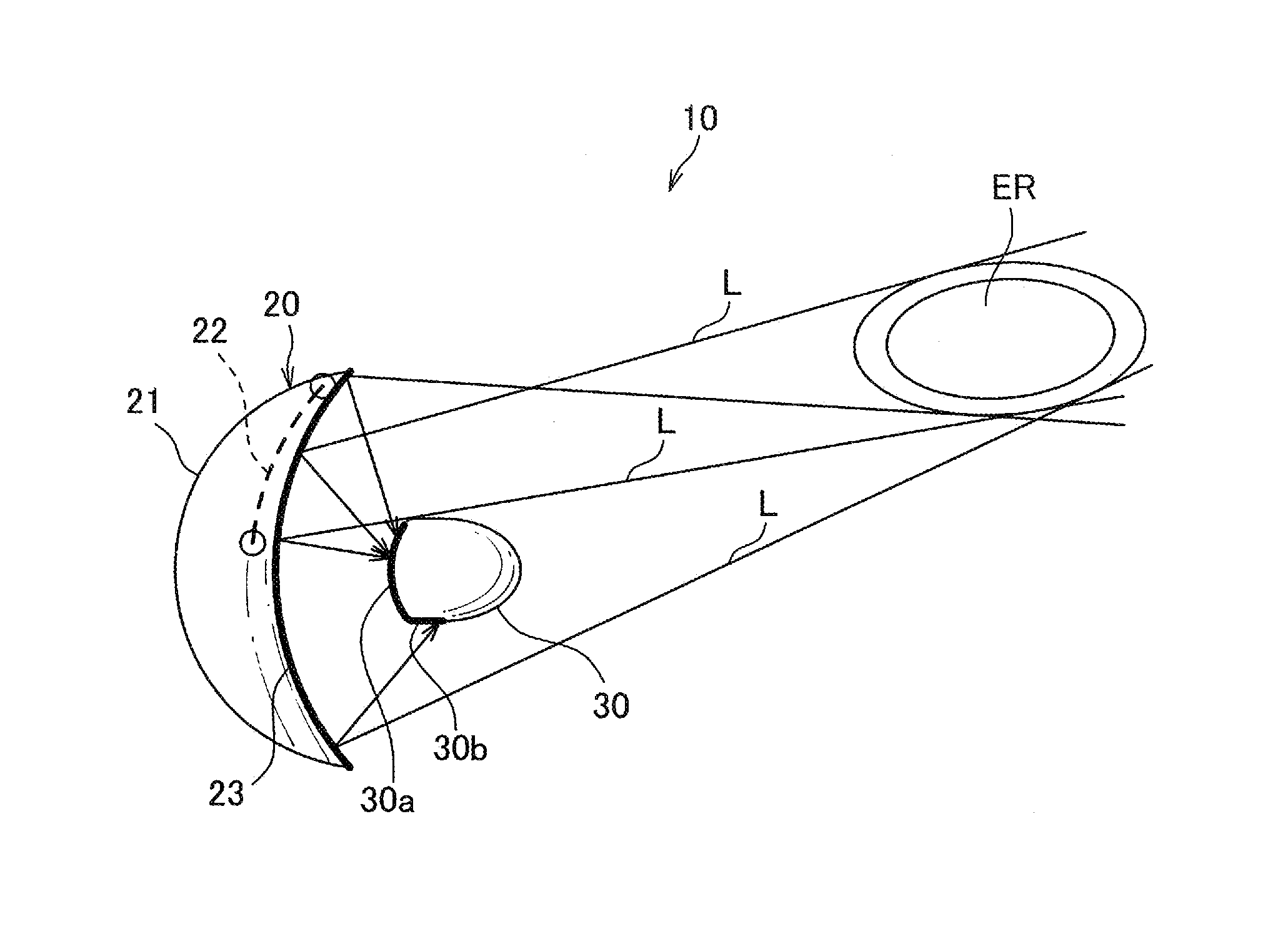
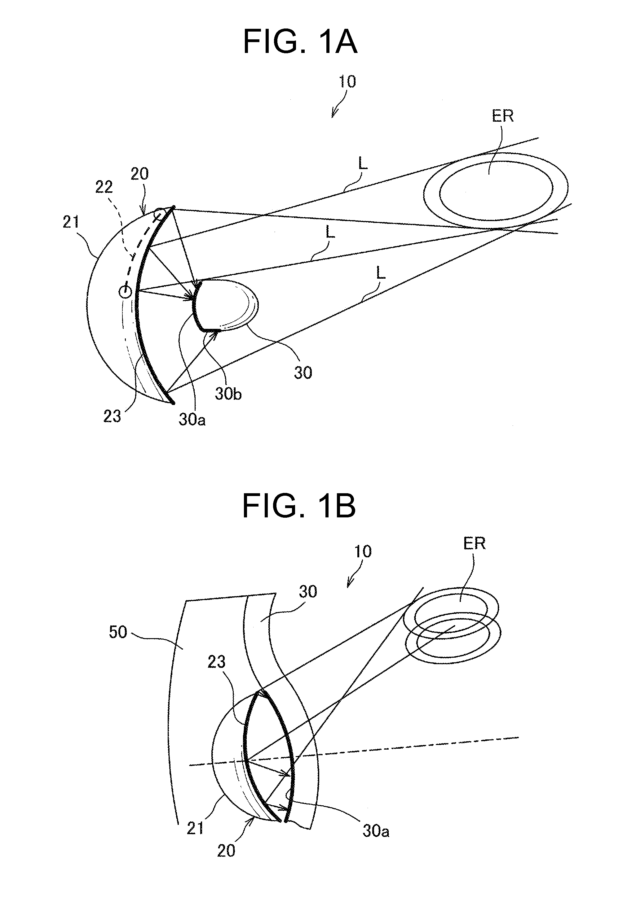
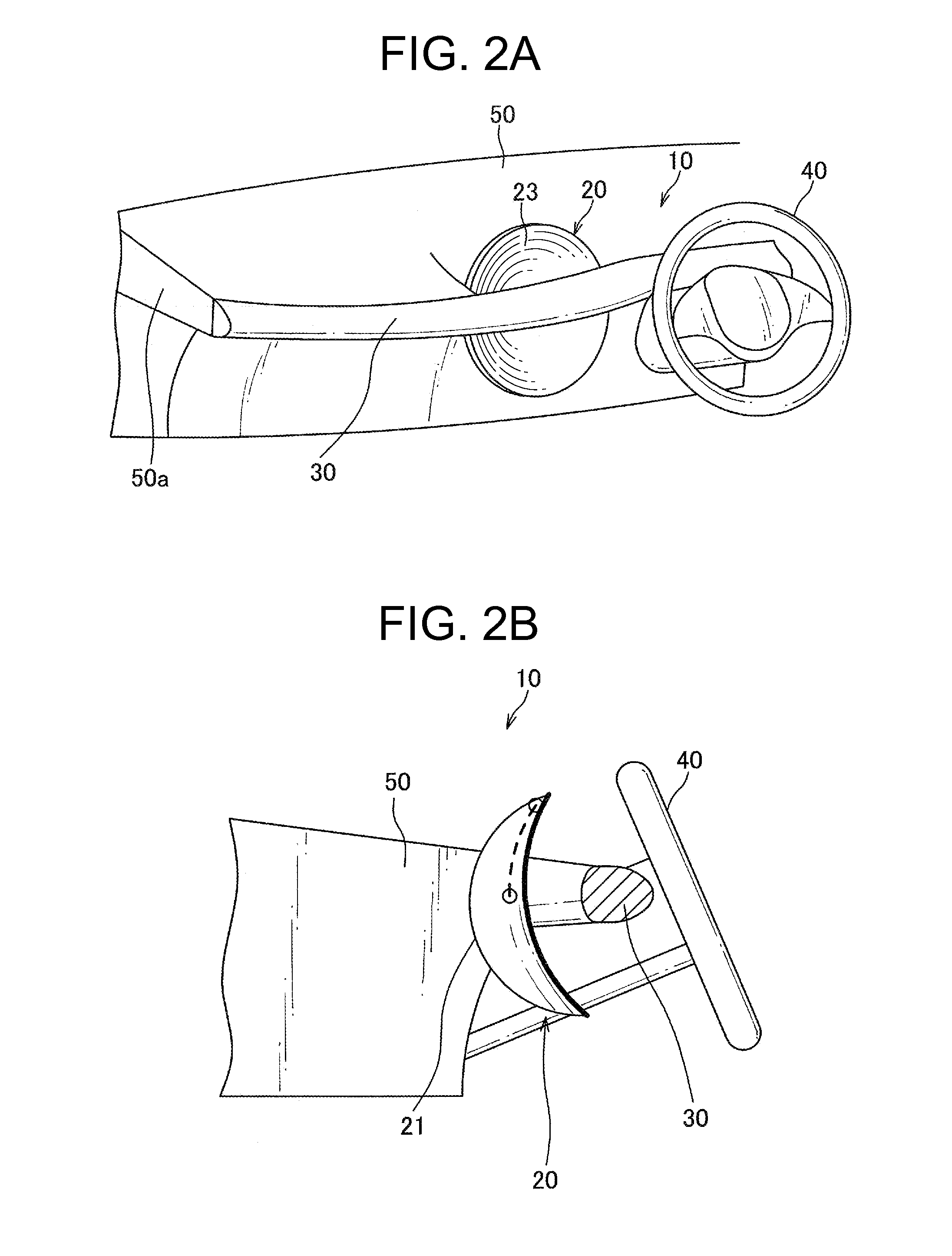
[0032]FIGS. 1A and 1B are diagrams schematically illustrating the configuration of a display apparatus for use in a vehicle according to a first embodiment of the invention, with FIG. 1A being a side view and FIG. 1B being a top view. FIGS. 2A and 2B are configuration diagrams illustrating the configuration of the display apparatus for use in a vehicle according to the first embodiment of the invention, with FIG. 2A being a perspective view and FIG. 2B being a side view.
[0033]With reference to FIGS. 1A and 1B, a display apparatus 10 for use in a vehicle includes an indicator unit 20 placed at an appropriate position in a vehicle (which is between an instrument panel [hereinafter referred to as IP]50 and a driver seat, and it is at a position diagonally in front of the driver seat in the present embodiment). The indicator unit 20 includes a housing 21, an indicator 22 accommodated in the housing 21, and a face glass sheet 23 attached to the housing 21 in such a manner that the indica...
second embodiment
[0043]FIG. 3 is a top view schematically illustrating the configuration of a display apparatus for use in a vehicle according to a second embodiment of the invention. While the indicator unit 20 in the first embodiment illustrated in FIGS. 1A and 1B is diagonally in front of the driver seat (for example, on a vehicle center line CL1), an indicator unit 20 according to the third embodiment is right in front of a driver (on a driver center line CL2). In other words, the indicator unit 20 may be placed at any position, such as at the center of a vehicle and in front of a driver.
third embodiment
[0044]FIGS. 4A and 4B are configuration diagrams schematically illustrating the configuration of a display apparatus for use in a vehicle according to a third embodiment of the invention, with FIG. 4A being a side view and FIG. 4B being a front view. In FIGS. 4A and 4B, a support 25 is illustrated, which is an exemplary support for supporting an indicator unit 20 at an appropriate position in a vehicle. The support 25 is made of, for example, synthetic resin and includes a pole 25a, a supporting body 25b, and supporting rods 25c. The pole 25a extends perpendicularly with one end thereof fixed to a position on a floor surface between an IP 50 and a driver seat inside the vehicle. The supporting body 25b is, for example, a spherical component attached to the other end of the pole 25a. The supporting rods 25c extend radially from the supporting body 25b and have ends that support the indicator unit 20 by fixing means, such as bonding and locking with locking pieces. The supporting body...
PUM
 Abstract
Description
Claims
Application Information
 - R&D
- Intellectual Property
- Life Sciences
- Materials
- Tech Scout
- Unparalleled Data Quality
- Higher Quality Content
- 60% Fewer Hallucinations
Browse by: Latest US Patents, China's latest patents, Technical Efficacy Thesaurus, Application Domain, Technology Topic, Popular Technical Reports.
© 2025 PatSnap. All rights reserved.Legal|Privacy policy|Modern Slavery Act Transparency Statement|Sitemap|About US| Contact US: help@patsnap.com


