
Hydraulic system for machine

Active Publication Date: 2016-01-28
CATERPILLAR GLOBAL MINING LLC
View PDF4 Cites 2 Cited by
  • Summary
  • Abstract
  • Description
  • Claims
  • Application Information

AI Technical Summary

Benefits of technology

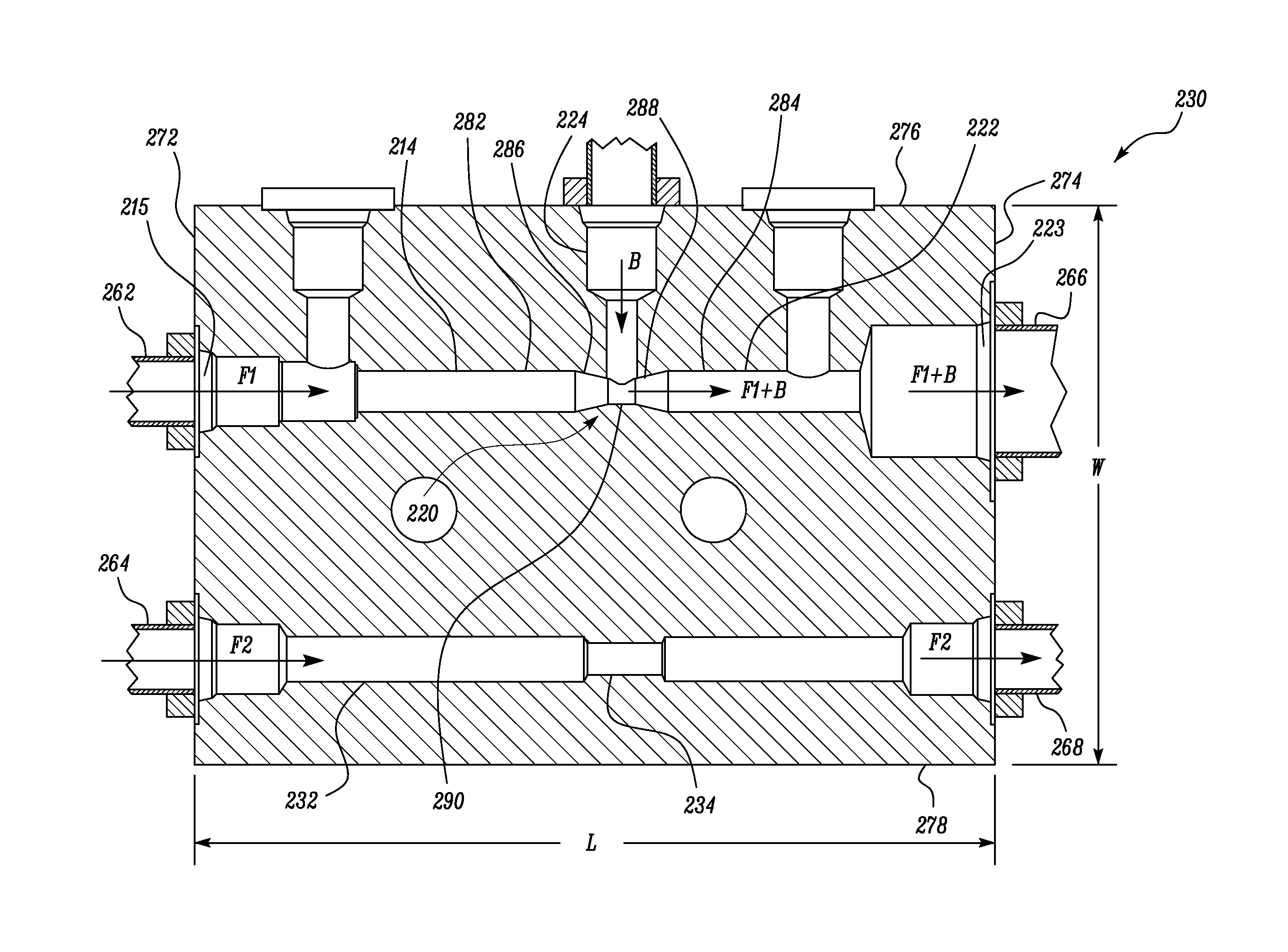
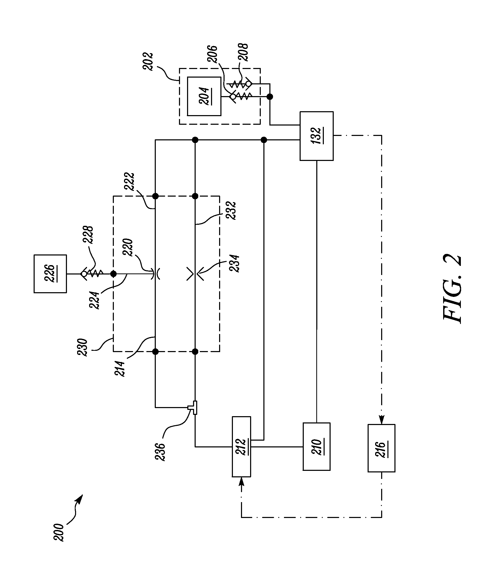
The present patent is about a hydraulic system for a machine that can increase the pressure of a liquid in a tank using a venturi and a gaseous fluid. This system includes a hydraulic tank, a first conduit to receive the liquid from the tank, a venturi to reduce the pressure of the liquid, and a fluid conduit to supply the gaseous fluid into the venturi. The system also includes a second conduit to supply the mixture of the liquid and gaseous fluid into the tank. This patent aims to provide a more efficient way to control the pressure of the liquid in the tank and to improve the performance of the machine's hydraulic system.

Problems solved by technology

The compressor may require maintenance and become unreliable after a long period of operation.
Further, in cold weather conditions, there may be a tendency of condensed water to freeze within the compressor.

Method used


Image

  • Hydraulic system for machine
  • Hydraulic system for machine
  • Hydraulic system for machine

Examples


Embodiment Construction

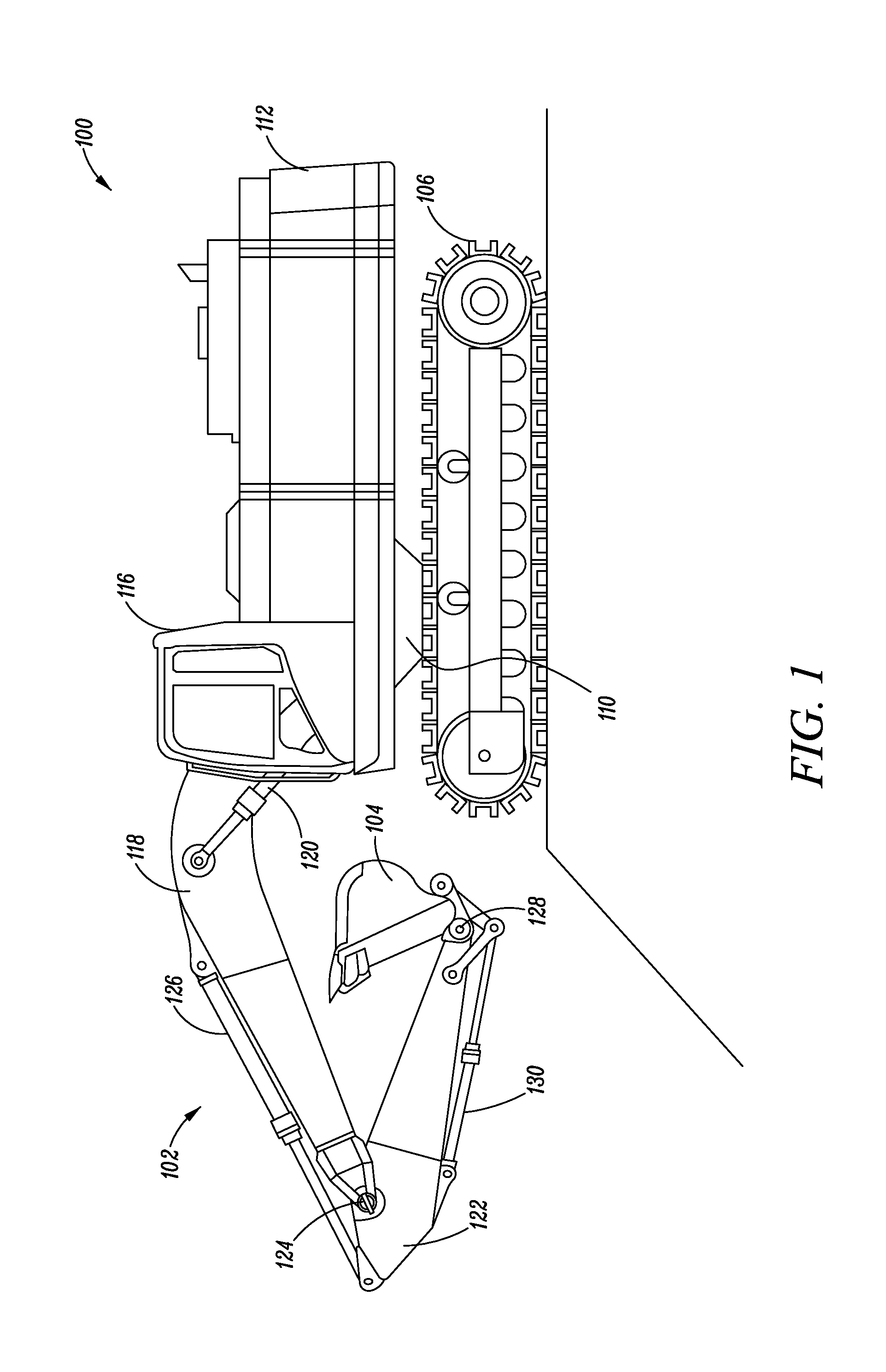
[0014]Wherever possible, the same reference numbers will be used throughout the drawings to refer to the same or the like parts. FIG. 1 illustrates a side view of a machine 100. The machine 100 may include an on-highway vehicle or an off-highway vehicle. Further, the machine 100 may include any machine that may be used for the purpose of construction, mining, quarrying, and so on. In the embodiment of FIG. 1, the machine 100 is a hydraulic mining shovel. The machine 100 may include an implement system 102 for performing various earth moving operations, such as digging, leveling, etc., through an implement 104.

[0015]The machine 100 may further include a ground engaging member 106 that may be drivably coupled to a drive system (not shown) of the machine 100. In the embodiment of FIG. 1, the ground engaging member 106 may be a pair of tracks. However, it may be contemplated that the ground engaging member 106 may be a plurality of wheels. The ground engaging member 106 may be disposed ...


PUM


Abstract

A hydraulic system for a machine is disclosed. The hydraulic system includes a hydraulic tank configured to store a liquid therein. The hydraulic system also includes a first conduit, a venturi, a fluid conduit and a second conduit. The first conduit is in fluid communication with the hydraulic tank and configured to receive the liquid from the hydraulic tank. The venturi is in fluid communication with the first conduit and configured to reduce a pressure of the liquid flowing therethrough. The fluid conduit is in fluid communication with the venturi and configured to supply a gaseous fluid into the venturi. The second conduit is in fluid communication with the venturi and configured to supply a mixture of the liquid and the gaseous fluid into the hydraulic tank in order to increase a pressure of the liquid in the hydraulic tank.

Description

TECHNICAL FIELD[0001]The present disclosure relates to a hydraulic system for a machine, and more particularly to a hydraulic system and a method of controlling the hydraulic system for a machine.BACKGROUND[0002]Machines such as those used for, construction, agriculture, transportation and mining, include various hydraulic actuators associated with one or more systems of the machines, for example, an implement system, a steering system, a brake system and the like. The hydraulic actuators may include hydraulic cylinders, hydraulic motors, and the like. One or more pumps supply the hydraulic actuators with pressurized hydraulic fluid for actuation. The pumps are connected to a hydraulic tank which stores the hydraulic fluid. The hydraulic fluid may be maintained at an elevated pressure within the hydraulic tank in order to meet the inlet fluid characteristic requirements of the pumps. Typically, a compressor is connected to the hydraulic tank to provide pressurized air to the hydraul...

Claims


Application Information

Patent Timeline
IPC IPC(8): F04D25/04F03B1/00
CPCF03B1/00F04D25/04E02F9/0883E02F9/226E02F9/2267F15B1/265
Inventor LUVAAS, JOHN, K.
Owner CATERPILLAR GLOBAL MINING LLC
Learn More