Eureka AIR delivers breakthrough ideas for toughest innovation challenges, trusted by R&D personnel around the world.

Cryogenic medical system

a medical system and cryogenic technology, applied in the field of cryogenic medical systems, can solve the problems of increasing the risk factors of other conditions such as embolism, tissue freezing, and the use of heat exchangers, and achieve the effects of reducing the temperature, increasing the fluid resistance, and reducing the flow of coolan

Active Publication Date: 2016-01-28
VARIAN MEDICAL SYSTEMS
View PDF0 Cites 28 Cited by
  • Summary
  • Abstract
  • Description
  • Claims
  • Application Information

AI Technical Summary

Benefits of technology

The patent describes a cryogenic medical system that uses supercritical cryogen to treat medical conditions, particularly cardiac arrhythmias such as atrial fibrillation. The system includes a cryoengine and cryoinstruments that can be used at multiple treatment sites. The system includes supply and return tubing, as well as connectors that can interconnect the different components of the system. The cryoinstruments can also have a telescoping feature that allows for easy positioning during treatment procedures. The system has a cryogenic supply console that is detachable from the cryoengine and can be transported to different treatment locations. The system can be adapted for both epicardial and endocardial treatments, making it a flexible and adaptable treatment option for atrial fibrillation.

Problems solved by technology

Further, the use of heat exchangers have been limited to coils placed into a bath of cryogen to allow for time consuming, inefficient passive subcooling of the cryogen in which activation of these devices circulate a cryogen (such as liquid nitrogen) to a probe to create a heat sink, thus resulting in tissue freezing.
One such category of diseases includes cardiac arrhythmias, a significant health problem.
Although atrial arrhythmias may not be as fatal as frequently as ventricular arrhythmias, atrial arrhythmias increase risk factors for other conditions such as embolisms.
Moreover, atrial fibrillation may be caused by abnormal activity within one or more focal centers within the heart, the electrical activity generally decreasing the efficiency with which the heart pumps blood.
However, creating lesions in a heart using cryotherapy poses a challenge in the delivering sufficient cooling to create a transmural (i.e., a through thickness) lesion.
In addition, blood delivered to and from the heart constantly provides heat to a target site at the heart, thereby counteracting the cooling being delivered by the cryotherapy and limiting the amount of cooling that can be delivered to the target site.
The device would address an important aspect of treatment by providing lesions, transmural and continuous in character (otherwise, segmenting the heart and preventing fibrillation would not be possible).
Even though visualization and positioning aids are adequate for general placement of the device, maintaining the device in a selected position and orientation can be difficult as the tissue moves and blood flows, especially during a procedure that must be done quickly.
In addition to the challenges presented by moving tissue and flowing blood, the actual topography of the tissue being treated presents challenges.
Thus, for procedures that call for uniform tissue contact or tissue contact along an extended line, the structure and techniques for use of known devices can be deficient in some regards.
Due to the nature and the anatomical constraints that are imposed on the procedure by the vasculature, each procedure will present unique issues for consideration.
In addition, recent studies have suggested that the cooling rate and subsequent warming rate can affect the percentage of tissue cells destroyed in a cryoablation procedure.
Radiofrequency energy, however, is not amenable to safely producing circumferential lesions without the potential for serious complications.
In particular, while ablating the myocardial cells, heating energy also alters the extracellular matrix proteins, causing the matrix to collapse.
Moreover, RF energy is known to damage the lining of the heart, which may account for thromboembolic complications, including stroke.
The use of RF energy for ablation can lead to untoward healing responses such as collagen build up at the area of interest after treatment.
In some cases, RF ablation may create lesions that cause occlusion of the coronary sinus in post procedure healing.
RF also causes significant radiation exposure.
Further, in cardiac settings, the heat sink provided by the blood pool creates a tremendous challenge to current cryoablation approaches as they cannot overcome this heat extraction hurdle.

Method used


Image

  • Cryogenic medical system
  • Cryogenic medical system
  • Cryogenic medical system

Examples


Embodiment Construction

[0057]In the following detailed description, for purposes of explanation and not limitation, exemplary embodiments disclosing specific details are set forth in order to provide a thorough understanding of the present invention. However, it will be apparent to one having ordinary skill in the art that the present invention may be practiced in other embodiments that depart from the specific details disclosed herein. In other instances, detailed descriptions of well-known devices and methods may be omitted so as not to obscure the description of the present invention.

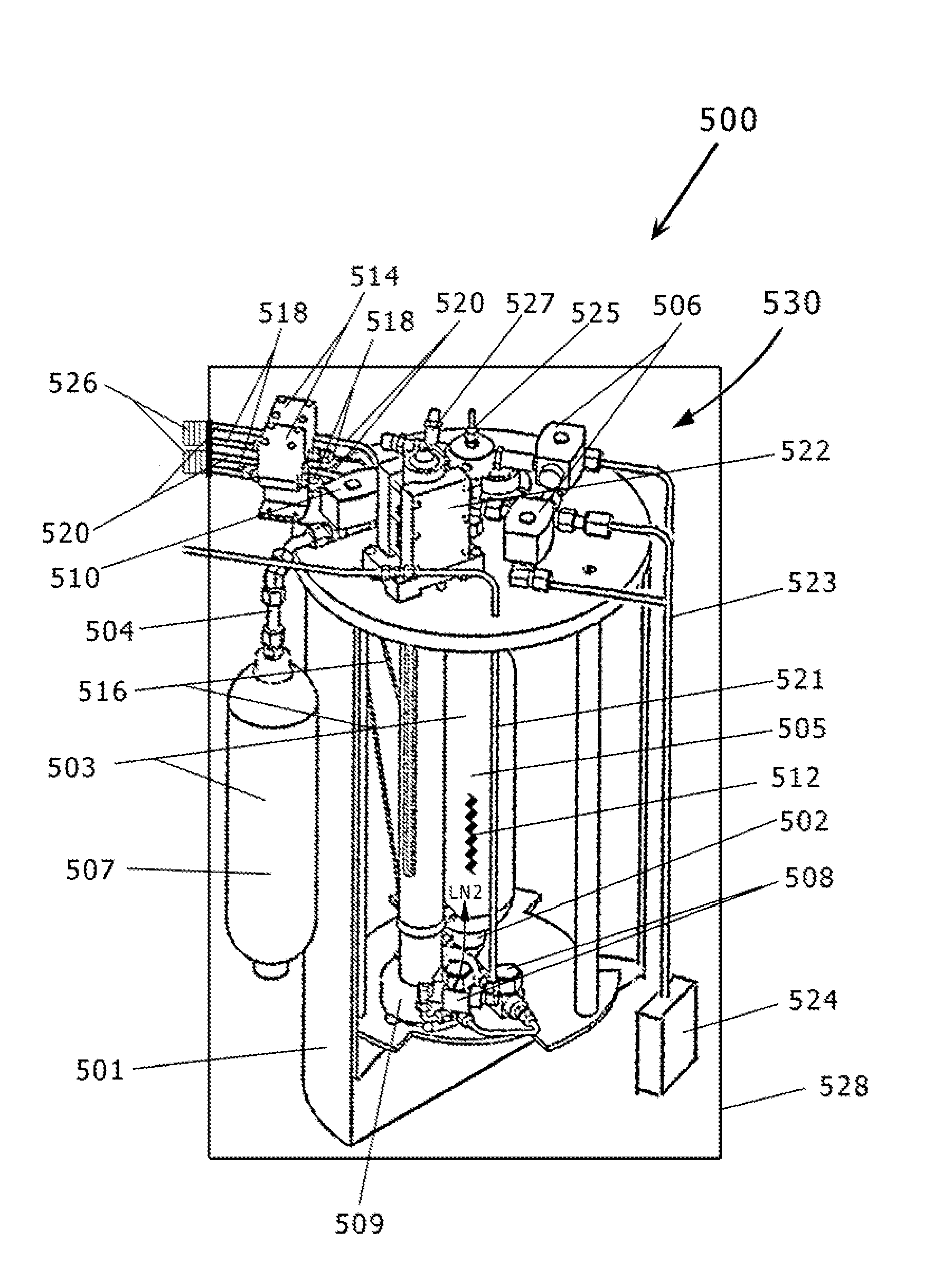
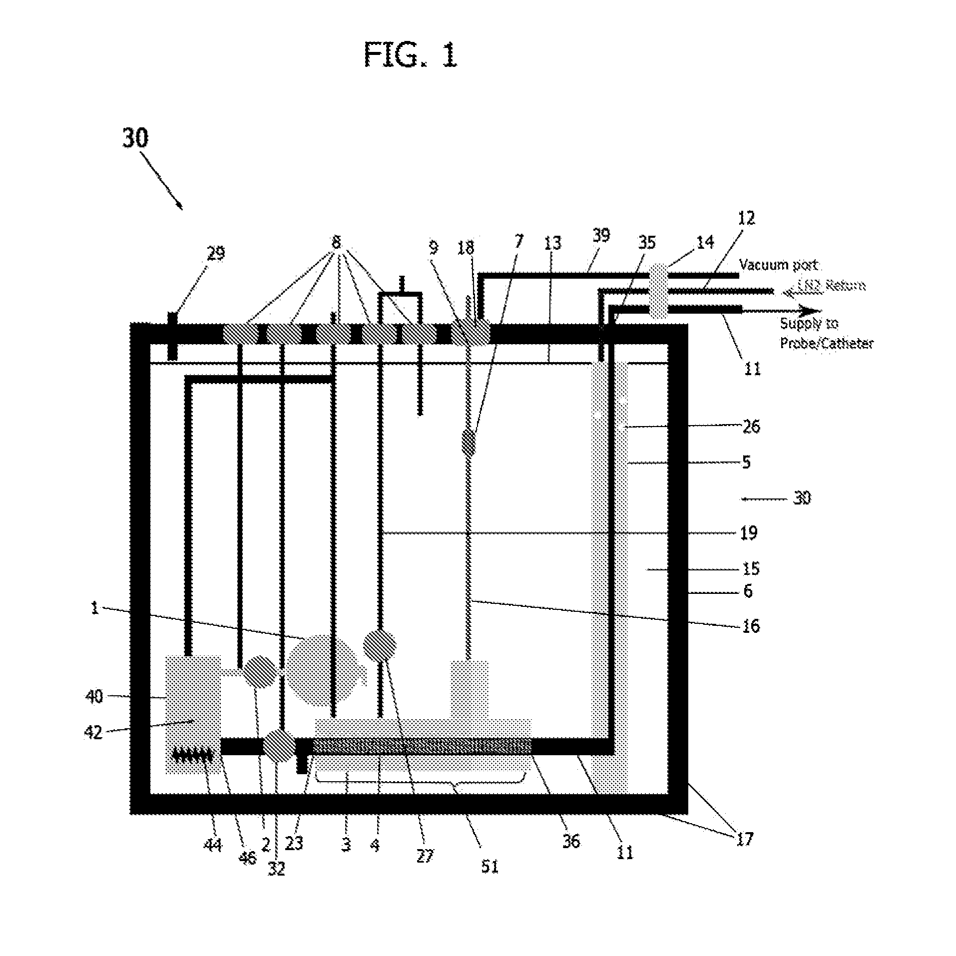
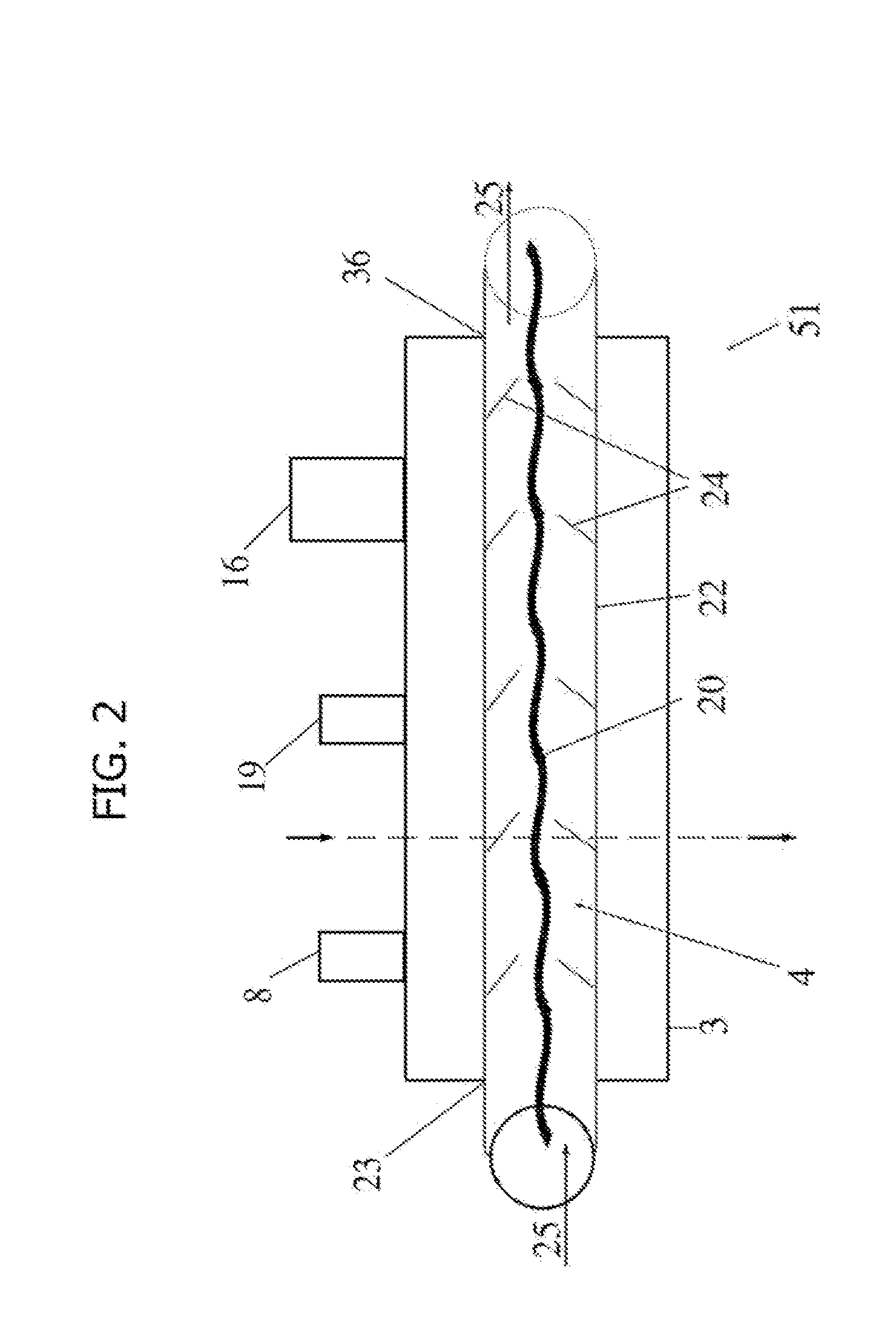
[0058]An external view of a device and system in accordance with one embodiment of the present invention is shown in FIG. 1. The cryogenic system or device 30 has sidewalls 17 which form a container 6 that encloses an internal cavity, or lumen 15. In an embodiment of FIG. 1, the container 6 takes the form of a vacuum insulated dewar 6. Any size or shape of insulated vessel, however, may be utilized as the dewar 6. The dewa...


PUM


Abstract

Cryogenic medical devices and apparatus are disclosed which are capable of generating cryogen to a supercritical state, specifically supercritical nitrogen. The cryogenic medical devices and apparatus disclosed are useful in methods of treating damaged, diseased, cancerous or other unwanted tissues.

Description

RELATED APPLICATIONS[0001]This application is a continuation application of U.S. Ser. No. 13 / 038,862, filed Mar. 2, 2011, now U.S. Pat. No. 9,089,316, which is a continuation-in-part application of PCT Application No. US2009 / 062928 filed on Nov. 2, 2009, which is a continuation-in-part application of U.S. Ser. No. 12 / 553,005 filed on Sep. 2, 2009, which claims the benefit of priority to U.S. Provisional Application Ser. No. 61 / 093,916 filed on Sep. 3, 2008.FIELD OF THE INVENTION[0002]The present invention relates generally to the medical technology field and, in particular, to a medical device for use in a cryogenic system as utilized to treat cardiac arrhythmias, such as in atrial fibrillation.BACKGROUND OF THE INVENTION[0003]Over a recent number of years, there has been a strong movement within the surgical community toward minimally invasive therapies. The main goals of the minimally invasive therapies include: 1) eradication of targeted tissue, 2) decreased hospitalization time,...

Claims


Application Information

Patent Timeline
Patent Type & Authority Applications(United States)
IPC IPC(8): A61B18/02
CPCA61B18/02A61B2018/00041A61B2018/00577A61B2018/0262A61B2018/00791A61B2018/00863A61B2018/00982A61B18/0218A61B2018/00773A61B2018/00351A61B2018/00011A61B2018/0293A61B2018/0212A61B2018/00357A61B2018/00994F04C2270/0421
Inventor BAUST, JOHN M.BAUST, JOHN G.CHEEKS, ROY E.DOBSON, MELISSA K.ROBILOTTO, ANTHONY T.SNYDER, KRISTI K.VAN BUSKIRK, ROBERT G.
Owner VARIAN MEDICAL SYSTEMS
Why Eureka
Eureka Blog
Learn More