Eureka AIR delivers breakthrough ideas for toughest innovation challenges, trusted by R&D personnel around the world.

Grid nozzle assembly, a fluidized bed reactor with a grid nozzle assembly and methods of using a grid nozzle assembly

Active Publication Date: 2016-01-21
AMEC FOSTER WHEELER ENERGIA
View PDF2 Cites 11 Cited by
  • Summary
  • Abstract
  • Description
  • Claims
  • Application Information

AI Technical Summary

Benefits of technology

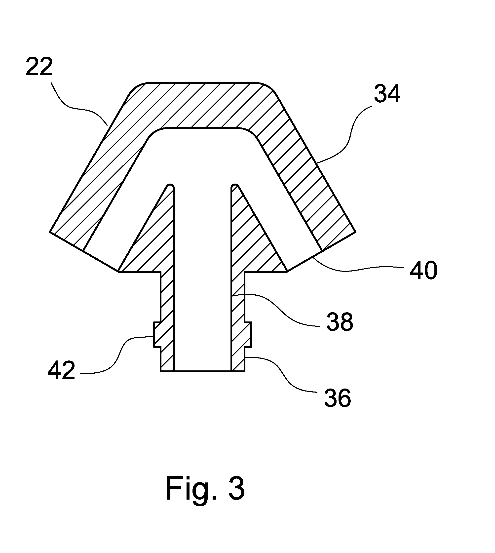
The present invention provides a grid nozzle assembly for a fluidized bed reactor that allows for quick and efficient connection and disconnection of the nozzle head and tube sleeve. The nozzle head and tube sleeve form a twist-lock to secure the nozzle head in place. The stem is designed to minimize damage to the tube sleeve and prevent fine bed particles from sticking to the nozzle head. The diameter of the gas flow path is constant throughout the vertical gas pipe and the vertical portion of the gas channel to avoid turbulence and erosion. The tube sleeve can be firmly fixed to the gas pipe before or after the nozzle head is tack-welded to it. The outer surface of the tube sleeve has flat surfaces to allow for firm holding while twisting the nozzle head without damaging the gas pipe.

Problems solved by technology

The conditions in the reaction chamber are often relatively harsh due to high temperatures, chemical attack of compounds formed in the reaction chamber or erosion caused by bed particles entrained with the fluidizing gas.
Due to the harsh conditions, there is often a need to regularly replace grid nozzles by new ones.
Thus, the nozzle heads are especially prone to deterioration.
Due to the ash, there is a risk for high velocity ash erosion to occur inside the grid nozzles, increasing the need for frequent maintenance.
This is a relatively slow process, which tends to each time shorten the remaining tube.
It also gives rise to a considerable amount of harmful metal debris, which has to be removed from the bottom grid.
Such a threaded nozzle head coupling is not suitable for many large scale fluidized bed reactors because the thread is relatively slow to open, and it may easily become stuck during the operation of the reactor.
This nozzle grid construction is also relatively slow to open and may deteriorate or become stuck during the operation.

Method used


Image

  • Grid nozzle assembly, a fluidized bed reactor with a grid nozzle assembly and methods of using a grid nozzle assembly
  • Grid nozzle assembly, a fluidized bed reactor with a grid nozzle assembly and methods of using a grid nozzle assembly
  • Grid nozzle assembly, a fluidized bed reactor with a grid nozzle assembly and methods of using a grid nozzle assembly

Examples


Embodiment Construction

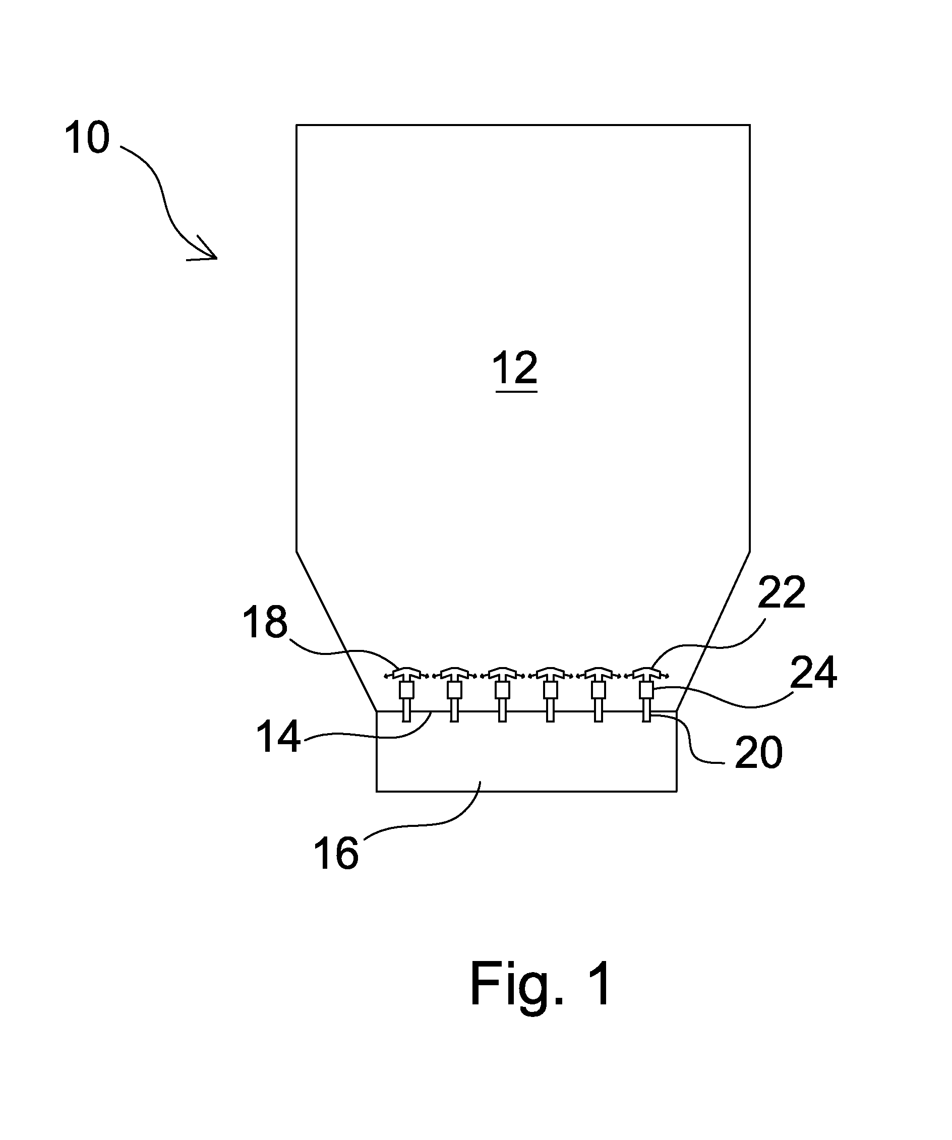
[0029]The schematic diagram of FIG. 1 shows a fluidized bed reactor 10 having a reaction chamber 12. The reaction chamber comprises a horizontally extending bottom plate 14 and a gas plenum chamber 16, so-called wind box, below the bottom plate. In the fluidized bed reactor 10, which can be, for example, a circulating or bubbling fluidized bed boiler or gasifier, chemical reactions are performed in the reaction chamber 12 in a fluidized bed of particles, such as sand or ash or fuel particles. The bed is fluidized by bringing fluidizing gas, such as combustion air, to the reaction chamber 12 from the wind box 16 through a bottom grid of the reaction chamber. The bottom grid comprises multiple grid nozzles 18 through which the fluidizing gas is injected in a predetermined, relatively high velocity and predetermined direction to the reaction chamber. In practice a fluidized bed reactor comprises also many other parts, such as fuel feeding nozzles, an exhaust gas channel etc. However, b...


PUM

PropertyMeasurementUnit
Angleaaaaaaaaaa
Angleaaaaaaaaaa
Angleaaaaaaaaaa

Abstract

A grid nozzle assembly for a fluidized bed reactor, a fluidized bed reactor with a grid nozzle assembly, a method of mounting a grid nozzle assembly as a replacement in a fluidized bed reactor, and a method of replacing a grid nozzle assembly in a fluidized bed reactor. The reactor includes a horizontally extending bottom plate, a gas plenum chamber below the bottom plate, and vertical gas pipes having a top end and extending from the gas plenum chamber upwards across the bottom plate. The nozzle assembly includes a nozzle head with a gas channel for injecting fluidizing gas from one of the vertical gas pipes to the reaction chamber and a tube sleeve adapted to be firmly fixed by welding around the top end of the vertical gas pipe. The nozzle head and the tube sleeve form a twist-lock enabling quick connecting and disconnecting.

Description

BACKGROUND OF THE INVENTION[0001]1. Field of the Invention[0002]The present invention relates to a grid nozzle assembly for a fluidized bed reactor, a fluidized bed reactor with a grid nozzle assembly, a method of mounting a grid nozzle assembly as a replacement in a fluidized bed reactor and a method of replacing a grid nozzle assembly in a fluidized bed reactor.[0003]2. Description of the Related Art[0004]In fluidized bed reactors, such as circulating or bubbling fluidized bed boilers or gasifiers, chemical reactions are performed in a reaction chamber in a fluidized bed of particles, such as sand or ash or fuel particles. The bed is fluidized by bringing fluidizing gas, such as combustion air, to the reaction chamber from a gas plenum chamber, usually so-called wind box, through a bottom grid of the reaction chamber. The bottom grid comprises grid nozzles through which the gas is injected in a predetermined, relatively high velocity and predetermined direction to the reaction cha...

Claims


Application Information

Patent Timeline
IPC IPC(8): B01J8/24B23K20/00B23K31/02
CPCB01J8/24B23K31/02B23K20/002B01J8/44B01J2208/00902F23C10/20F26B3/082F27B15/10
Inventor CAMPANELLA, RONKHAN, TANVEERGARGONE, PATRICKMUSGROVE, ROBERT
Owner AMEC FOSTER WHEELER ENERGIA
Why Eureka
Eureka Blog
Learn More