Timestamping detected radiation quanta

a detection and quanta technology, applied in radiation measurement, instruments, measurement devices, etc., can solve the problems of unit generation of timestamps, false triggering of timing units, and loss of detection accuracy, so as to improve discrimination and repeatable timing performance

Active Publication Date: 2016-01-14
KONINKLJIJKE PHILIPS NV
View PDF1 Cites 13 Cited by
  • Summary
  • Abstract
  • Description
  • Claims
  • Application Information

AI Technical Summary

Benefits of technology

[0028]According to another aspect of the invention, in the radiation detection device a pixel cell trigging rate for the one or more pixel cells within the optical detector array is determined within a time interval in the range 0.001 ns to 200 ns subsequent to the detection of one or more optical photons by pixel cells within the optical detector pixel array. The detection of a particular number of optical photons prior to the determination of the rate permits the triggering from a predetermined point in the profile of the optical pulse thereby providing repeatable timing performance.
[0029]According to another aspect of the invention a radiation detection device further includes a validation logic unit. The validation uni...

Problems solved by technology

False triggering of the timing unit is a problem that can arise in systems employing so-called direct detection, as well as in systems employing indirect detection such as PET imaging systems, and is particularly acute in such which employ digital silicon photomultiplier (SiPM) detectors operating in the Geiger mode as the optical detector.
Digital SiPM detectors suffer from dark count noise which manifests itself as spurious electrical pulses at the output of the optical detector in the absence of a valid event such as an optical pulse or a received gamma photon.
The electrical pulses from dark count noise are frequently misinterpreted by the timestamp trigger unit and falsely cause the timing unit to generate a timestamp.
Such false triggering results in a timing unit deadtime, a period of time during which the timing unit must be reset and during which it is unable to determine the time of reception of valid events.
Dark count noise is strongly temperature dependent, and even at room temperatures can create considerable timing unit deadtime.
This however has limited benefit...

Method used


Image

  • Timestamping detected radiation quanta
  • Timestamping detected radiation quanta
  • Timestamping detected radiation quanta

Examples


first embodiment

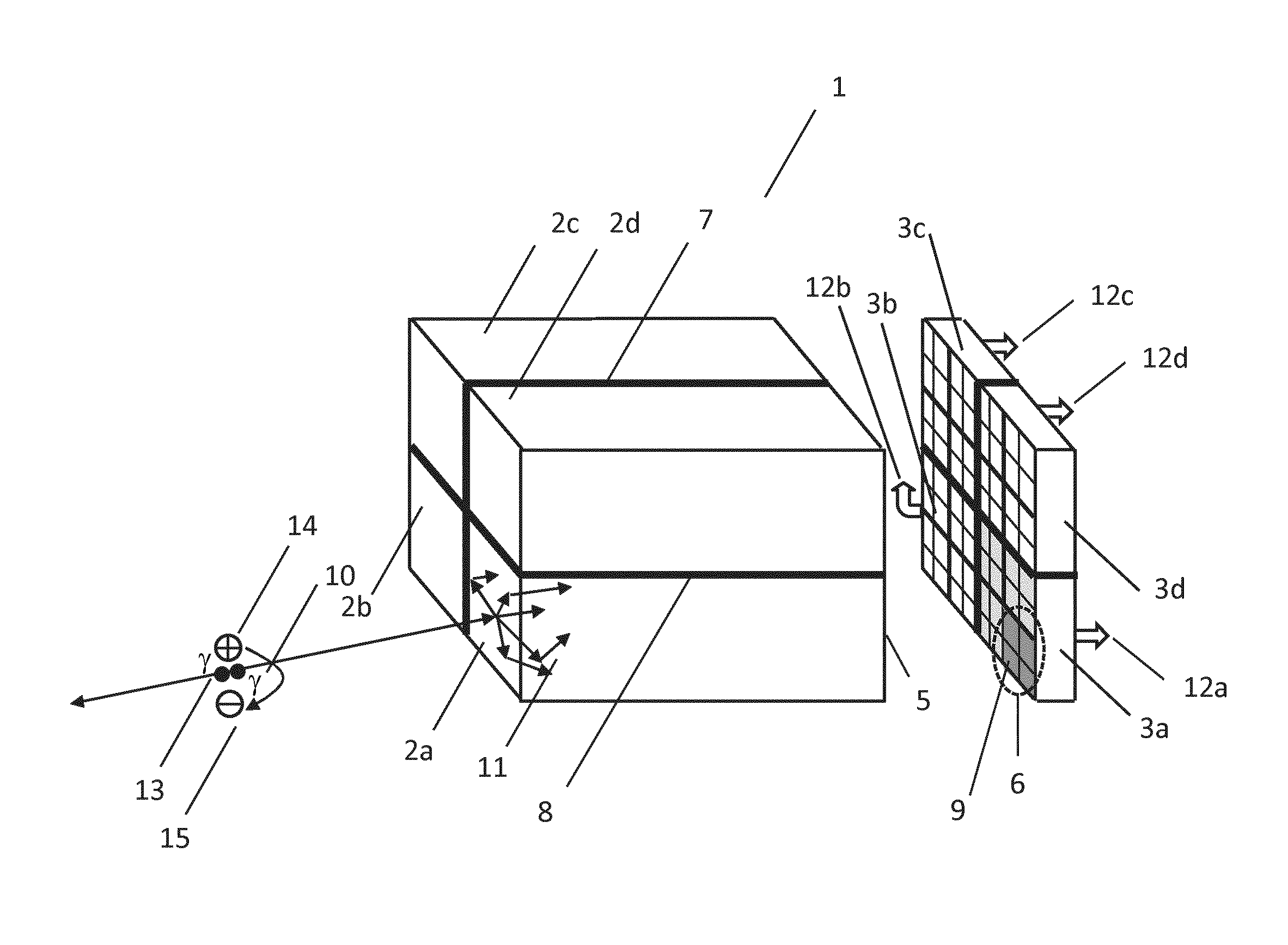
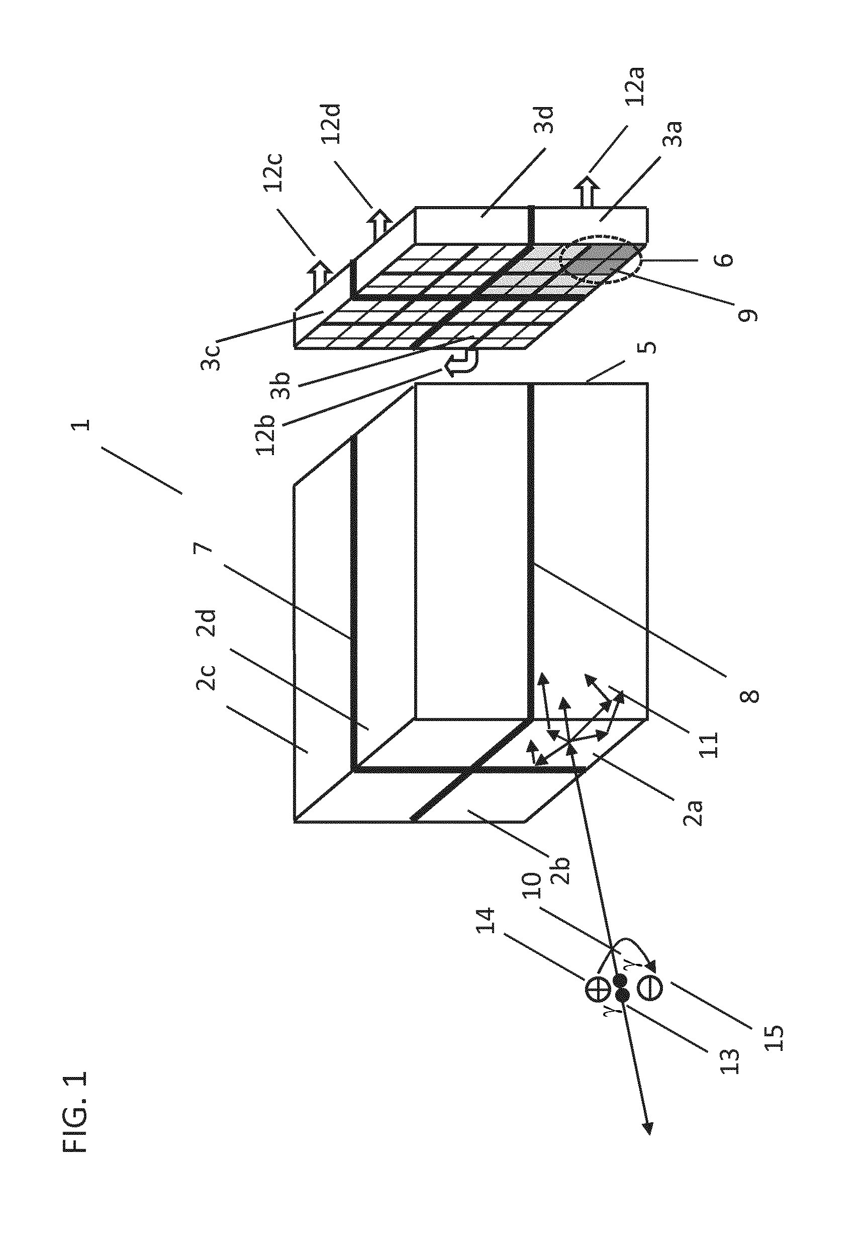
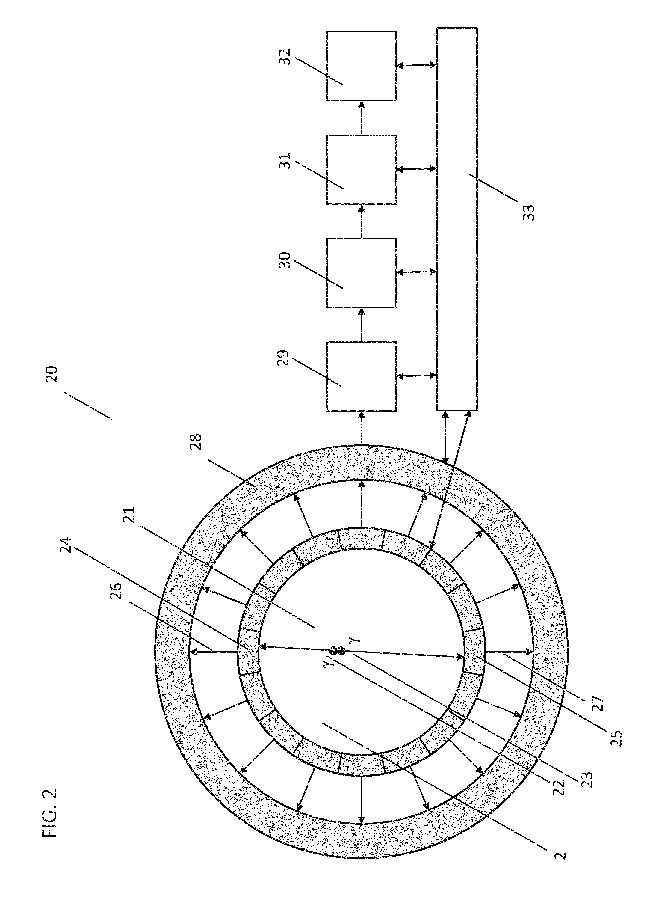
[0047]FIG. 4 illustrates a timing unit and timestamp trigger unit 71 in accordance with certain aspects of the invention. In FIG. 4, scintillator element 40 is in optical communication with optical detector pixel array 41 to form a gamma photon detector. Scintillation light generated within scintillator element 40 is detected by optical detector pixel array 41. A plurality of such gamma photon detectors may be used in the PET imaging system 20 illustrated in FIG. 2. Optical photons from for example Cherenkov radiation may be directly detected in the same way although in the absence of scintillator element 40. Optical detector pixel array 41 comprises one or more optical detector pixels, each comprising one or more pixel cells. A pixel cell may be a single optical photon avalanche detector (SPAD), otherwise known as a silicon photomultiplier (SiPM), and may be operated in the Geiger mode in which the reception of an optical photon results in the breakdown of the junction and a logica...

second embodiment

[0058]The embodiment in FIG. 5 may be configured to take advantage of the observation that a scintillation light pulse generated in a scintillator element 40 following the reception of a gamma photon is typically characterized by a rapid initial optical photon detection rate followed by a reduction in the optical photon detection rate. Such a profile is typical of a scintillation light pulse from a gamma photon in a PET imaging system in which a rapid initial increase in scintillation light is followed by an exponential decay. The decay constant may be in the order of 40 ns. By contrast the profile from dark count noise, which is randomly generated, results in a more uniform pixel cell triggering rate. Optical photons from for example Cherenkov radiation may be directly detected in the same way as described above although in the absence of scintillator element 40. These characteristic differences in the pixel cell triggering rate may be exploited in the second embodiment illustrated...

fourth embodiment

[0064]In an example implementation of the fourth embodiment, the circuit in FIG. 5 is configured such that the monostables in pulse shortener unit 51 each have a period of 0.5 ns, delay unit 56 has a delay period of 1 ns and delay unit 61 has a delay period of 10 ns. Furthermore output 57 of primary trigger logic 54 is configured to be in a logical true state when any one of its inputs from pulse shortener unit 51 are in a logical true state. Output 70 of secondary trigger logic unit 55 is configured to be in a logical true state when the number of pixel cells triggered in optical detector pixel array 41 during the 1 ns period of delay unit 56 corresponds to a gamma photon reception rate exceeding 106 counts per second. Output 69 of tertiary trigger logic unit 63 is configured to be in a logical true state when the number of triggered cells in optical detector pixel array 41 during the 10 ns period of delay unit 61 corresponds to a gamma photon reception rate exceeding 105 counts pe...


PUM


Abstract

The present invention relates to a radiation detection device, a system, a method and a computer program product for use in timestamping detected radiation quanta. The device comprises an optical detector pixel array, a timestamp trigger unit and a timing unit. The timestamp trigger unit determines a pixel cell triggering rate for pixel cells within the optical detector pixel array. The timestamp trigger unit causes the timing unit to generate a timestamp based on the pixel cell triggering rate.

Description

FIELD OF THE INVENTION[0001]The present invention relates to the timestamping of detected radiation quanta and finds application in high energy particle physics applications. Such applications encompass the direct detection of radiation quanta in the form of optical photons such as Cherenkov radiation, as well as the indirect detection of radiation quanta by means of the optical photons produced by a scintillator element. The invention finds particular application in PET imaging systems, and even more particularly the invention can be used in time-of-flight (TOF) PET imaging systems.BACKGROUND OF THE INVENTION[0002]In PET imaging a radiotracer is administered to a subject such as a patient or an animal prior to its positioning in the PET imaging region. The radiotracer is preferentially absorbed by regions in the subject and its distribution is imaged following an uptake period. Subsequently a clinician interprets the relative uptake in particular regions in the images such as organ...

Claims


Application Information

Patent Timeline
IPC IPC(8): G01T1/16G01T1/20G01T1/29
CPCG01T1/1606G01T1/20G01T1/2985G01T1/171
Inventor SOLF, TORSTEN
Owner KONINKLJIJKE PHILIPS NV
Why Eureka
Try Eureka