
Dental abutment, abutment and screw assembly, and dental implant system

a technology of dental implants and screws, applied in dental prosthetics, dental surgery, medical science, etc., can solve the problems of thread breaking off the shaft, increasing the risk of screw loosening or breaking, and increasing the risk of screw loosening, etc., to achieve the effect of reducing radial thickness, increasing the diameter of the screw, and tightening the screw torqu

Inactive Publication Date: 2016-01-14
TERRATS TRIQUELL MONTSERRAT
View PDF3 Cites 2 Cited by
  • Summary
  • Abstract
  • Description
  • Claims
  • Application Information

AI Technical Summary

Benefits of technology

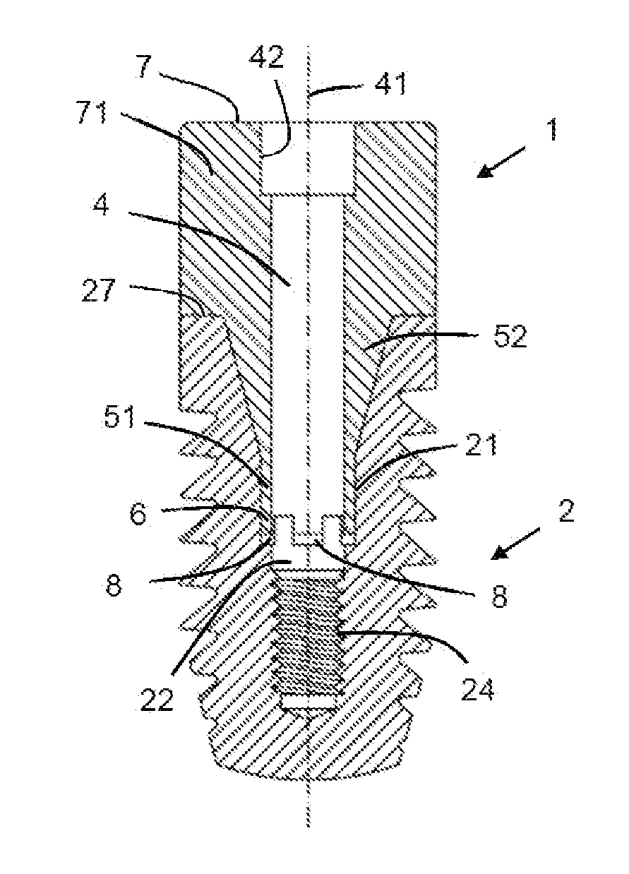
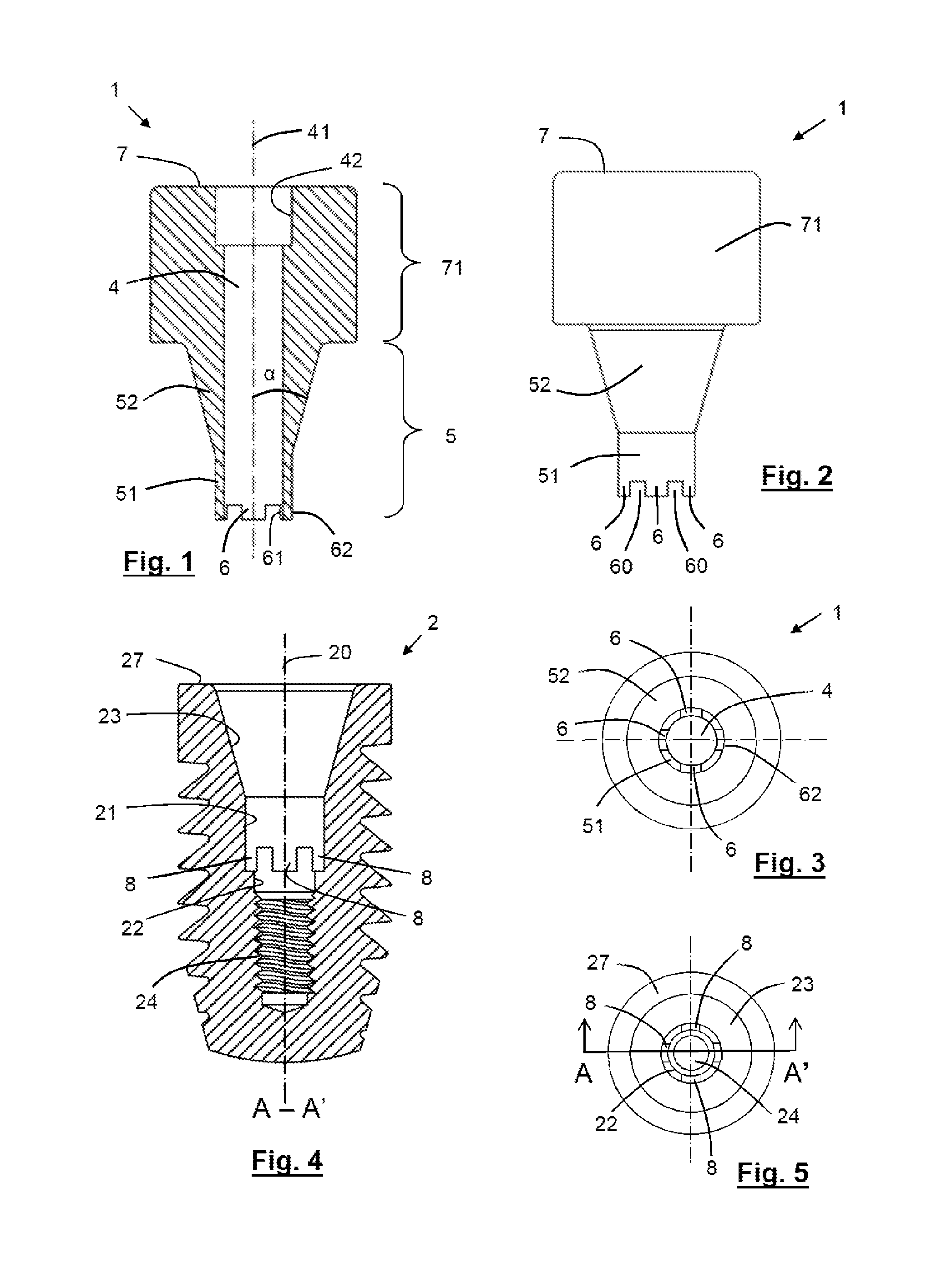
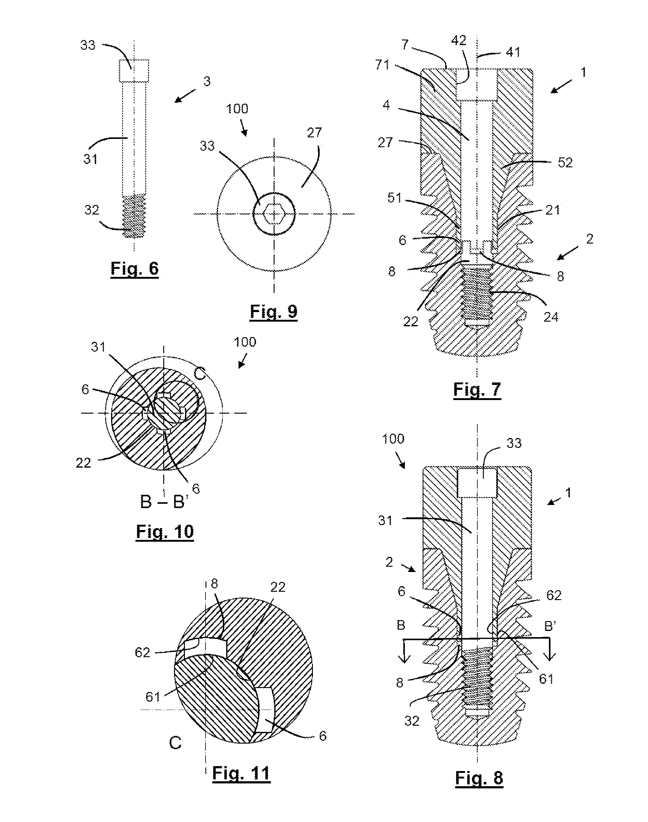
The abutment in this implant system allows for a connection design that can be used with different types of implants on the market. It features anti-rotation means that are inserted into grooves on the implant and abutment. The abutment is designed to have a maximum diameter of the fixing screw, ensuring reliability and security against fragility. The use of merlons with a suitable length and curved shape offer rigidity to the implant system. The screw is a single piece, which offers an advantage over welded alternatives.

Problems solved by technology

The formation of these simple or complex geometric figures requires considerable radial space, taking into account the reduced dimensions of a dental implant.
However, and due to the mentioned space limitation, occasionally implants are manufactured which for assembly with their corresponding abutments, require screws formed by two welded pieces, in which a piece with the thread cutting is welded to the shaft piece of the screw, which adds a more fragile element to the system and the risk of the thread breaking off the shaft and being housed in the interior of the implant with the consequent problems which it would cause.
Among the problems which can arise in these types of connections are those of loosening or breakage of the screw and, although less frequent, the breakage of the implant itself, triggered for reasons such as breakage due to fatigue or loosening, often produced by bruxism of the patient.

Method used


Image

  • Dental abutment, abutment and screw assembly, and dental implant system
  • Dental abutment, abutment and screw assembly, and dental implant system
  • Dental abutment, abutment and screw assembly, and dental implant system

Examples


Embodiment Construction

[0014]With the aim of providing a solution to the drawbacks set out, a dental abutment is made known configured at one of its ends for the internal connection to a dental implant and for the fixing to the same by means of a fixing screw. The abutment is provided, apically at its connection end, with anti-rotation means for positioning and fixing the orientation of the abutment with respect to the implant to which it is intended to be connected, and of a through-hole configured for the passage therethrough of the fixing screw, the axis of which extends in the longitudinal direction to the apical connection end.

[0015]In essence, the dental abutment is characterised in that the anti-rotation means comprise a plurality of longitudinal protrusions separated from each other, which extend in the direction parallel to the axis of the through hole at the apical connection end, the protrusions being equidistant with respect to said axis and being configured as merlons such that the separation...


PUM


Abstract

The invention relates to a dental abutment with internal connection to an implant and fixing by means of a fixing screw. The abutment is provided, apically at the connection end thereof with anti-rotation means for positioning and fixing the orientation of the abutment with respect to the implant, and with a through hole configured for the passage therethrough of the fixing screw, the axis of which extends in the longitudinal direction to the apical connection end. The anti-rotation means comprise a plurality of longitudinal protrusions separated from each other which extend in the direction parallel to the axis of the through hole at the apical connection end, the protrusions being equidistant with respect to said axis and being configured as merlons such that the separation space between two adjacent protrusions is connected to the through hole.

Description

TECHNICAL SECTOR OF THE INVENTION[0001]The present invention relates to a dental prosthetic abutment, such as a pillar of cicatrisation, a prosthetic pillar, an impression tray, etc., which are coupled by an internal connection to a dental implant and are fixed by means of a fixing screw. The abutment is provided with anti-rotation means for positioning and fixing the orientation of the abutment with respect to the implant to which it is intended to be connected.[0002]The invention also relates to a dental abutment and fixing screw assembly, as well as to a dental implant system which comprises the cited assembly and a corresponding dental implant.BACKGROUND OF THE INVENTION[0003]The osseointegration capacity of titanium has been well-known since the middle of the 20th century and from the studies published by the professor, Per-Ingvar Bråemark, therefore said characteristic has enabled a multitude of reconstruction solutions for lost dental pieces, notably improving the masticatory...

Claims


Application Information

Patent Timeline
Patent Type & Authority Applications(United States)
IPC IPC(8): A61C8/00
CPCA61C8/0068A61C8/0069A61C8/0054A61C8/0066A61C8/0001A61C8/008A61C13/00
Inventor TERRATS TRIQUELL, MONTSERRATTERRATS BES, RAMONBOSCH BRILLAS, AMADEU
Owner TERRATS TRIQUELL MONTSERRAT
Learn More